Wiring a wall switch to control a standard duplex receptacle is one of the most common residential electrical tasks, but the exact wiring diagram depends entirely on whether you want the switch to control the entire outlet or just half of it. For a standard living room or bedroom where a wall switch controls a floor lamp while the bottom half remains live for a vacuum or phone charger, you need a half-switched (split) outlet. This requires a 3-wire cable (14/3 or 12/3 NM-B), breaking the brass fin on the receptacle, and landing specific wire colors on specific brass and silver terminals.
The Direct Answer: Switch-to-Outlet Wiring Decision Path
Before stripping any wire, use this decision tree to lock in your exact materials and wiring topology. Do not guess; pick the scenario that matches your room's functional requirement.
| Scenario | Functional Goal | Cable Required | Receptacle Tab Status |
|---|---|---|---|
| A: Fully Switched | Switch controls both top and bottom sockets (e.g., dedicated appliance or single lamp). | 14/2 NM-B (or 12/2) | Leave brass tab INTACT. |
| B: Half-Switched (Split) | Switch controls top socket; bottom socket is always hot (e.g., lamp + vacuum). | 14/3 NM-B (or 12/3) | BREAK the brass (hot) tab. |
Mains Safety & Required Tools
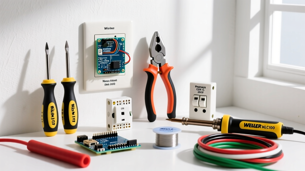
Gathering the correct tools prevents damaged terminals and loose connections that cause arc faults later.
- Wire: 14/3 NM-B (for 15A circuits) or 12/3 NM-B (for 20A circuits). Ensure it is copper, not aluminum.
- Devices: Leviton 5262-W (15A duplex receptacle) and a 15A single-pole switch (e.g., Leviton 5601-W).
- Strippers: Klein Tools 11057 (strips 12-22 AWG solid/stranded without nicking the copper).
- Testers: Fluke 117 True-RMS Multimeter and a Klein NCVT-3 Non-Contact Voltage Tester.
- Drivers: Insulated screwdrivers (#2 Robertson/square and #2 Phillips) and a torque screwdriver set to 14 in-lbs (Leviton's spec for 14 AWG).
Wire Gauge and Device Rating Sizing
The gauge of your wire and the amp rating of your receptacle must match the breaker protecting the circuit. A common and dangerous botch is installing a 15A receptacle on a 20A breaker using 12 AWG wire without verifying the receptacle's feed-through rating.
- 15A Breaker Circuit: Use 14 AWG wire minimum. You may use 15A or 20A rated receptacles. (Default to 15A receptacles like the Leviton 5262-W to save money and box space).
- 20A Breaker Circuit: Use 12 AWG wire minimum. You must use 20A rated receptacles (like the Leviton 5362-W) OR 15A receptacles only if there is more than one receptacle on the entire circuit (per NEC 210.21(B)(3)).
For this guide, we assume a standard 15A circuit using 14/3 NM-B. A 15A circuit can safely handle up to 1,800 watts (15A × 120V), but per the NEC 80% rule for continuous loads (on for 3 hours or more), you should limit continuous draw to 1,440 watts. Standard lamps and vacuums are non-continuous loads, so the full 1,800W is available.
Step-by-Step: Wiring a Half-Switched (Split) Outlet
This sequence assumes you are wiring both the switch box and the outlet box, with the 14/3 NM-B cable running between them. The power source (14/2 NM-B) enters the switch box first.
- Prepare the Cable Ends: Strip exactly 3/4 inch of insulation off the ends of the black, red, and white wires using your wire strippers. Do not nick the copper. Leave the bare copper ground wire at 3/4 inch as well.
- Break the Brass Tab (Outlet Box Only): On the side of the Leviton duplex receptacle with the brass-colored screws, locate the small metal fin connecting the top and bottom screws. Use your needle-nose pliers to bend this brass tab back and forth until it snaps off completely. Leave the silver tab on the opposite side completely intact. This physically isolates the top hot bus bar from the bottom hot bus bar.
- Terminate the Always-Hot (Outlet Box): Take the Black wire from the 14/3 cable and loop it clockwise around the bottom brass screw on the receptacle. Tighten to 14 in-lbs. This provides constant 120V power to the bottom socket.
- Terminate the Switched-Hot (Outlet Box): Take the Red wire from the 14/3 cable and loop it clockwise around the top brass screw on the receptacle. Tighten to 14 in-lbs. This will deliver 120V to the top socket only when the wall switch is closed.
- Terminate the Neutral (Outlet Box): Take the White wire from the 14/3 cable and land it on either of the silver screws. Because the silver tab is intact, one white wire feeds both the top and bottom sockets. Tighten to 14 in-lbs.
- Terminate the Ground (Outlet Box): Loop the Bare copper wire around the green grounding screw at the bottom of the receptacle yoke. If you are using a metal box, you must also run a 14 AWG bare copper pigtail from the box's ground clip to the receptacle's green screw.
- Wire the Switch (Switch Box): In the switch box, the incoming power (Black from 14/2 source) connects to the bottom brass screw on the single-pole switch. The Black wire of the 14/3 cable (going to the outlet's always-hot) is wire-nutted directly to the incoming source Black wire. The Red wire of the 14/3 cable (the switched load) connects to the top brass screw on the switch. All white wires in the switch box are wire-nutted together and pushed to the back. All bare grounds are wire-nutted together with a pigtail to the switch's green ground screw.
Verify and Test: Meter Readings & The Most Common Botch
Do not push the devices into the wall boxes and screw on the faceplates until you have verified the circuit logic with a multimeter. Restore power at the breaker panel.
Expected Meter Readings
Set your Fluke multimeter to AC Voltage (V~). Insert the black probe into the neutral slot (the longer vertical slot) and the red probe into the hot slot (the shorter vertical slot) of the receptacle.
- Bottom Socket (Switch OFF): 120V AC (Nominal range: 114V - 126V).
- Top Socket (Switch OFF): 0V AC.
- Top Socket (Switch ON): 120V AC.
- Neutral to Ground (Either socket): Less than 2V AC (Ideally 0.0V to 0.5V. Anything over 2V indicates a loose neutral or overloaded shared neutral elsewhere in the house).
The Most Common Botch: Breaking the Wrong Tab
The single most frequent error DIYers make when attempting a half-hot outlet diagram is breaking the silver (neutral) tab instead of, or in addition to, the brass (hot) tab.
The Fix: De-energize the circuit immediately. Remove the receptacle. Inspect the silver side. If the tab is missing, the receptacle is ruined and must be thrown away; you cannot safely solder or jumper a broken neutral tab on a standard residential receptacle. Install a new Leviton 5262-W, ensuring only the brass fin is removed.
Code Compliance and Final Installation
According to the National Fire Protection Association (NFPA) NEC Article 406.4, all 15A and 20A, 125V receptacles installed in dwelling units must be tamper-resistant (TR). Ensure the receptacle you purchase has the "TR" stamp on the yoke; the internal shutters prevent children from inserting objects into a single slot.
Furthermore, NEC Article 210.12 requires Arc-Fault Circuit Interrupter (AFCI) protection for nearly all 120V branch circuits supplying outlets in dwelling unit living rooms, bedrooms, and hallways. If you are replacing an existing outlet on an older circuit that lacks an AFCI breaker, upgrading the breaker in the main panel to an AFCI model is required by modern code standards when altering the circuit. For comprehensive residential electrical safety guidelines, refer to the U.S. Consumer Product Safety Commission (CPSC) Electrical Safety Center.
Once your meter readings confirm correct operation and the ground path is verified, carefully fold the wires into the box. Push the 14/3 NM-B cable to the back, fold the white neutrals neatly behind the device, and seat the receptacle flush against the drywall. Secure the yoke with the provided #6-32 machine screws, ensuring the device does not sit crooked. Snap on a standard single-gang nylon wall plate. The installation is complete, safe, and ready for load.