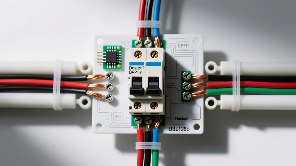
A tilt switch application in home electrical and appliance systems primarily serves as a gravity-activated safety interlock. Its job is to cut power when a device—like a 1500W portable space heater, a floor-standing air conditioner, or a garage hoist—exceeds a safe operating angle, typically between 30° and 45°. While legacy designs relied on toxic mercury capsules, modern 2026 appliances use RoHS-compliant rolling-ball mechanisms or solid-state dual-axis MEMS sensors paired with internal relays.
When wiring or replacing these interlocks, the most critical mistake is misreading the load ratings or ignoring the inductive kickback on the control side. Below is the exact framework for selecting, wiring, and testing tilt-activated relay modules in residential and light-commercial circuits.
Understanding Tilt Switch Ratings and Load Governance
Most heavy-duty tilt switches used in mains-voltage appliances are actually tilt-interlock relay modules. They contain the physical tilt sensor (which handles low-current logic) and an internal electromechanical relay (which switches the mains load). When reading the datasheet, you will see multiple rating columns. The Motor or Inductive column always governs for compressors, fans, and solenoids. Never use the Resistive rating for a motor load.
| Parameter | Resistive Load (AC) | Inductive Load (AC) | Motor Load (AC) | DC Breaking Capacity |
|---|---|---|---|---|
| Coil Voltage (Control) | 12V DC / 24V DC / 120V AC (Model Dependent) | |||
| Continuous Contact Rating | 10A @ 120V AC | 7A @ 120V AC | 1/3 HP @ 120V AC | 2A @ 24V DC |
| Inrush / Making Capacity | 15A | 30A | 45A (LRA) | 5A |
| Breaking Capacity | 10A | 5A | 1/3 HP | 2A |
A resistive load (like a nichrome heating element) draws a steady current. A motor load, however, draws Locked Rotor Amps (LRA) that can be 6 to 8 times the running current for the first few hundred milliseconds. If you size the tilt switch based on the 10A resistive column and connect it to a 9A compressor, the inrush current will pit and eventually weld the contacts shut, defeating the safety interlock entirely.
Wiring the Coil vs. Contact Side
A tilt-interlock module has two electrically isolated circuits: the coil side (the control circuit that energizes the relay based on the tilt sensor's logic) and the contact side (the dry contacts that switch the mains load).
The Contact Side (Mains Load)
Wire the Line (hot) conductor to the Common (COM) terminal, and the Load (switched hot) to the Normally Open (NO) terminal. When the appliance is upright, the internal sensor closes, energizing the relay and passing power to the NO terminal. If the appliance tips, the sensor opens, de-energizing the relay and dropping the load. Always use a minimum of 14 AWG copper wire for 15A branch circuits, and torque the terminal screws to the manufacturer's spec (typically 0.5 to 0.8 Nm) to prevent high-resistance heating.
The Coil Side (Control Circuit)
The coil side is often driven by a low-voltage DC control board (e.g., 12V or 24V DC). When switching an inductive relay coil with a DC transistor or microcontroller GPIO, you must manage the inductive transient. According to fundamental inductor transient response principles, collapsing the magnetic field in the coil generates a massive reverse-voltage spike.
If your tilt module's coil is driven by a DC control board, you must wire a flyback diode (e.g., 1N4007) in reverse-bias across the coil terminals (cathode to positive, anode to negative). Failing to do so will send a 100V+ spike back into your control board, instantly bricking the driving transistor or microcontroller.
Selection Decision Path by Load Type
Use this decision tree to select the correct tilt switch application module based on the appliance you are wiring or repairing.
| Load Type | Appliance Examples | Inrush Multiplier | Governing Rating Column | Required Module Spec |
|---|---|---|---|---|
| Resistive | Space heaters, toasters, incandescent lamps | 1.0x to 1.2x | Resistive (AC) | Standard 10A/15A AC rating |
| Inductive | Solenoid valves, contactor coils, transformers | 3x to 5x | Inductive (AC) | High breaking capacity, TV-5 rated |
| Motor | Portable AC compressors, fans, garage hoists | 6x to 8x (LRA) | Motor / Horsepower (AC) | HP-rated contacts, arc suppression |
Overcurrent Protection Note: When protecting the downstream motor load, do not treat fuses and breakers as interchangeable. A fast-acting ceramic fuse (e.g., 5x20mm) is required to clear short-circuits within milliseconds, while a thermal-magnetic breaker handles sustained overloads based on its specific time-current curve. Swapping a fast-blow fuse for a standard breaker without checking the let-through current and trip curve can result in welded tilt-switch contacts during a fault.
Testing and Diagnostics: Dead, Live, and Replacement Criteria
Troubleshooting a suspected tilt switch failure requires a systematic approach. Never assume the switch is faulty without verifying the mechanical angle and the electrical continuity.
How to Test It Dead (De-energized)
- De-energize and Verify: Turn off the branch breaker and verify zero voltage at the appliance terminals with a Category III multimeter.
- Continuity Check: Place your meter leads across the COM and NO terminals. Set the meter to continuity (audible beep).
- Angle Verification: Keep the appliance perfectly level. The meter should read near 0 ohms (closed). Slowly tilt the appliance. Note the exact angle where the meter reads OL (open loop). Compare this to the manufacturer's trip-point spec (usually 35° ± 5°). If it trips at 15° or requires 60° to trip, the internal rolling ball track is fouled with debris or the spring is fatigued.
How to Test It Live (Energized)
Live testing checks for voltage drop and contact degradation under load. Exercise extreme caution around exposed mains voltage.
- Power the appliance and force it into its normal running state.
- Set your multimeter to AC Volts.
- Place one probe on the Line terminal and the other on the Load terminal of the tilt switch.
- A healthy, closed contact will show a voltage drop of less than 50 millivolts (0.05V). If you read 2V to 5V across the closed contacts, the internal contacts are heavily pitted and generating dangerous heat. Use an infrared thermometer to verify; a terminal running 20°C above ambient under normal load is failing.
When to Repair vs. Replace
Always replace; never repair. Tilt switches are critical life-safety interlocks. The NFPA reports that portable heating equipment is a leading cause of home fire deaths, often due to failed tip-over switches. If the housing is cracked, the contacts are pitted, or a legacy mercury capsule is broken, the entire module must be swapped with an exact OEM or UL-listed equivalent. Do not attempt to file down pitted contacts or bend the internal actuator arm; you will alter the trip-angle geometry and compromise the fire safety of the appliance.
Frequently Asked Questions
What is the most common tilt switch application in portable home heating?
The most common application is the anti-tip-over interlock in 120V, 1500W portable ceramic or oil-filled radiator space heaters. In these units, a weighted rolling-ball tilt switch is wired in series with the main thermostat and the heating element relay. If the heater is knocked over by a pet or child, gravity pulls the ball away from the contacts, instantly breaking the 12.5A circuit before the heating element can ignite nearby carpeting or curtains.
Why does my tilt switch fail prematurely on an inductive compressor load?
Premature failure on compressor loads (like in portable air conditioners) is almost always caused by sizing the switch for the Running Load Amps (RLA) instead of the Locked Rotor Amps (LRA). When the compressor starts, it draws a massive inrush current. If the tilt switch is not specifically rated for 'Motor' or 'Pilot Duty' loads, the electrical arc generated when the switch opens will melt the internal contacts, causing them to weld together. Always use a tilt switch module with an HP (Horsepower) rating that matches or exceeds the compressor's HP.
Can I bypass a broken tilt switch application interlock to keep my appliance running?
No. Bypassing, jumpering, or defeating a tilt switch safety interlock is a severe fire and electrocution hazard. If a space heater or portable AC tips over while the interlock is bypassed, the heating element or hot compressor will remain energized against the floor or wall, rapidly leading to a structure fire. If the OEM replacement part is on backorder, the appliance must remain unplugged and out of service until the correct UL-listed interlock module is installed.