
The Critical Role of Post-Connection Verification
Connecting an electrical outlet might appear to be a straightforward task, but failing to rigorously verify the installation before and after energizing the circuit can lead to catastrophic arc faults, equipment damage, or severe shock hazards. According to the National Fire Protection Association (NFPA), electrical failures or malfunctions consistently rank among the leading causes of residential structure fires. As we navigate the 2026 NEC cycle updates, which place even stricter emphasis on torque verification and AFCI/GFCI protection, the margin for error has effectively reached zero.
This comprehensive inspection and testing guide details the professional protocol for verifying your work after connecting an electrical outlet. We will bypass basic DIY guesswork and focus on the exact diagnostic matrices, mechanical tolerances, and advanced troubleshooting techniques used by licensed electrical contractors.
Phase 1: Pre-Energization Visual and Mechanical Inspection
Before you ever flip the breaker to the 'ON' position, a rigorous mechanical inspection is mandatory. The majority of outlet failures stem from poor physical connections rather than incorrect wiring topology.
Torque Specification Compliance
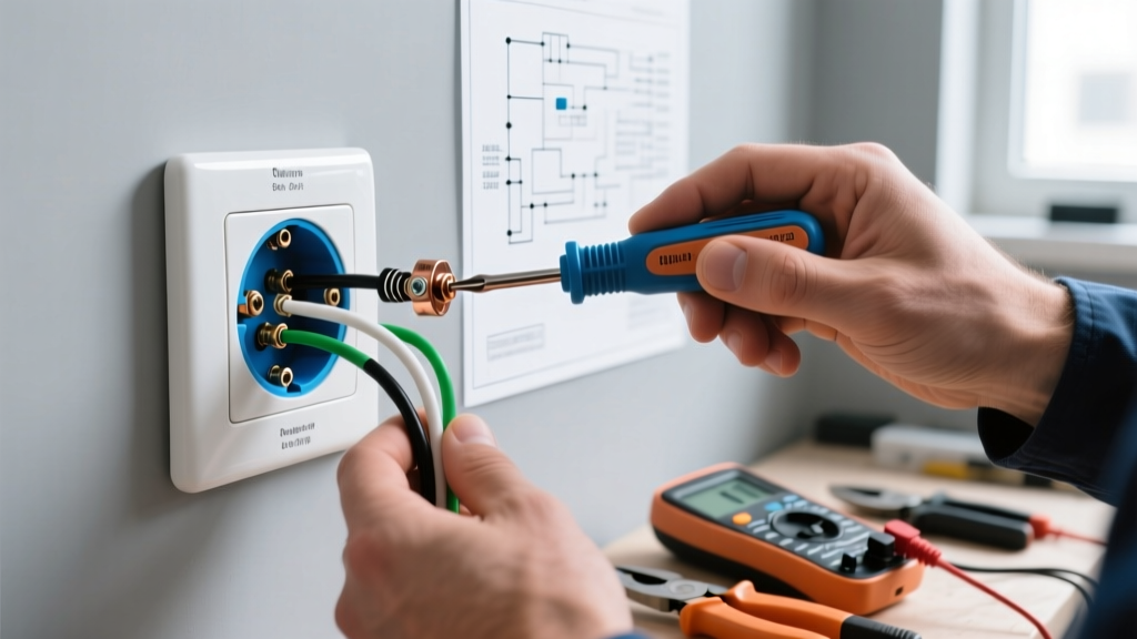
The National Electrical Code (NEC) Section 110.14(D) requires that terminations be tightened to the manufacturer's specified torque. For standard 15A and 20A duplex receptacles (such as the Leviton 5362 or Hubbell 5320), the terminal screws typically require between 14 and 16 inch-pounds (in-lbs) of torque. Using a calibrated torque screwdriver, like the Klein Tools 708 or CDI 401SM, ensures the wire is clamped securely without stripping the brass threads or damaging the conductor.
Wire Stripping and Loop Geometry
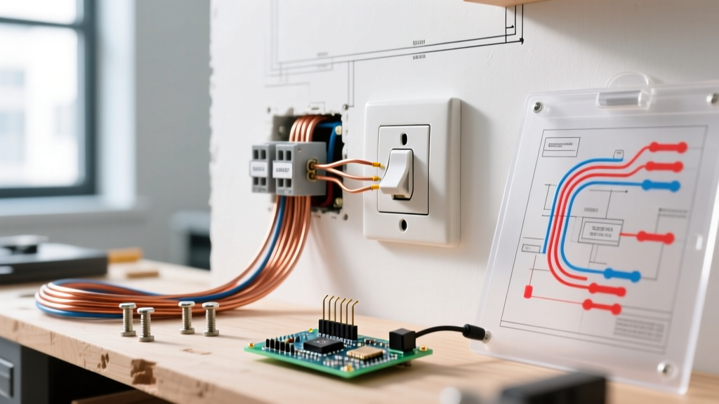
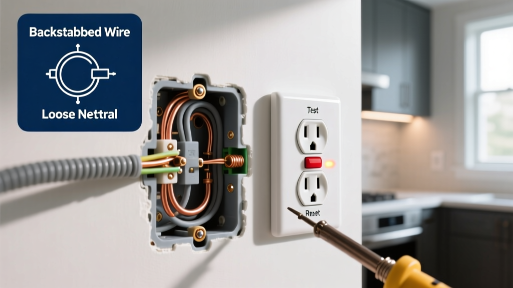
When utilizing side-wiring (loop and screw) methods, the wire insulation should be stripped to exactly 3/4 of an inch. If the strip is too short, the insulation will bind under the screw head, causing a high-resistance connection. If it is too long, exposed copper will protrude past the terminal, creating a shock hazard and a potential short-circuit point against the metal device box. Furthermore, the loop must be formed clockwise so that tightening the screw draws the loop closed rather than pushing it outward.
Box Fill and Conductor Bending Radius
Verify that the electrical box is not overfilled. According to NEC Article 314, a standard single-gang plastic nail box (typically 18 to 22 cubic inches) can comfortably hold two 12/2 NM cables and one 15A or 20A receptacle. Forcing excess wire into the box can pinch the insulation against the metal mounting yoke or the drywall, leading to latent ground faults.
Phase 2: Selecting Professional Diagnostic Equipment
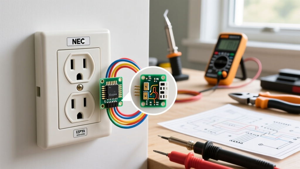
While a standard $12 neon receptacle tester can identify basic wiring faults like reverse polarity, it is entirely inadequate for modern inspection standards. These inexpensive tools cannot detect 'bootleg grounds' (where the ground terminal is illegally jumpered to the neutral) or measure actual voltage drop under load.
- Digital Multimeter (DMM): A true-RMS multimeter like the Fluke 117 or T6-1000 is essential for measuring exact voltage differentials and verifying the presence of stray voltages via FieldSense technology.
- Advanced Receptacle Tester: The Klein Tools RT210 or Amprobe AT-3500 provides digital readouts of line voltage, GFCI trip times, and can actively test AFCI breakers at the panel.
- Thermal Imager: A pocket thermal camera, such as the FLIR TG165, is critical for post-load verification to detect microscopic heat anomalies at the terminal connections.
Phase 3: Live Voltage and Polarity Testing Matrix
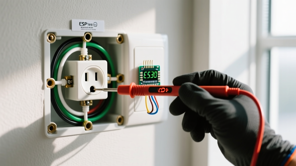
Once the breaker is energized, you must measure the voltage at the receptacle slots. The ANSI C84.1 standard dictates that a nominal 120V circuit should operate within a range of 114V to 126V. Use your True-RMS multimeter to record the following three measurements.
| Measurement Points | Expected Voltage | Acceptable Range | Fault Indication if Out of Range |
|---|---|---|---|
| Hot (Short Slot) to Neutral (Long Slot) | 120.0 V | 114 V - 126 V | Open neutral, high-resistance splice, or overloaded circuit. |
| Hot (Short Slot) to Ground (U-Shape) | 120.0 V | 114 V - 126 V | Open ground, bootleg ground, or miswired panel neutral/ground bond. |
| Neutral (Long Slot) to Ground (U-Shape) | 0.0 V | 0 V - 2 V | Voltage drop from heavy loading, shared neutral overload, or floating neutral. |
Expert Insight: If your Hot-to-Neutral reads 120V, but your Neutral-to-Ground reads 4V or higher, you have excessive voltage drop on the neutral conductor. This often occurs on long branch circuits using 14 AWG wire carrying near-capacity loads (e.g., 14A on a 15A circuit). The Occupational Safety and Health Administration (OSHA) frequently cites improper voltage drop and overloaded neutrals in commercial electrical inspections due to the fire risk posed by overheated conductors.
Phase 4: GFCI and AFCI Functional Trip Testing
If the outlet you are connecting is a Ground Fault Circuit Interrupter (GFCI) or is downstream of an Arc Fault Circuit Interrupter (AFCI) breaker, functional testing is legally required by the NEC.
GFCI Threshold Testing
A standard Class A GFCI receptacle must trip when the ground fault current reaches between 4mA and 6mA. Using the 'TEST' button on the device only verifies that the mechanical relay functions; it does not verify the actual milliamp sensitivity or the integrity of the ground path. You must use an external tester like the Klein RT210 to inject a precise fault current. Furthermore, test the GFCI under a loaded condition (e.g., with a 10A hair dryer running) to ensure the internal electronics do not fail under thermal stress.
AFCI Branch Circuit Verification
For outlets protected by an AFCI breaker at the panel, use a tester capable of generating the specific high-frequency arc signature required to trip the breaker. Note that many older AFCI testers will not trip modern 2026-era combination AFCI breakers due to updated algorithmic filtering designed to prevent nuisance tripping from vacuum cleaners and power tools. Always verify the specific testing procedure outlined by the breaker manufacturer (e.g., Square D HOMCAF or Eaton BRCAF).
Phase 5: Advanced Troubleshooting and Edge Cases
Even experienced electricians encounter anomalous readings when connecting an electrical outlet. Here is how to diagnose the most deceptive edge cases.
The 'Bootleg Ground' Deception
In older homes, a previous DIYer may have installed a jumper wire between the neutral and ground terminals on a 3-prong outlet to trick standard testers into showing a 'Correct Wiring' light. To expose this dangerous fault, measure the voltage between Hot and Neutral, and then Hot and Ground. If both read exactly the same (e.g., 121.3V), and the Neutral-to-Ground reads absolute zero, you likely have a bootleg ground. To confirm, turn off the breaker, remove the receptacle cover, and visually inspect the terminals for a jumper wire. The Consumer Product Safety Commission (CPSC) warns that bootleg grounds are lethal, as a loose neutral will instantly energize the metal chassis of any plugged-in appliance.
Multi-Wire Branch Circuits (MWBC)
If you are connecting an outlet in a kitchen or bathroom, you may encounter an MWBC (two hot wires sharing a single neutral). If you break the hot-side brass tab to split the receptacle for two different circuits, you MUST ensure the two hot wires are on opposite phases (240V between them). If they are on the same phase, the shared neutral will carry the sum of both loads (e.g., 15A + 15A = 30A), instantly overheating the 14 AWG or 12 AWG neutral wire and creating a severe fire hazard inside the wall.
Post-Load Thermal Verification
The final step in professional inspection occurs after the circuit has been under load for at least 15 minutes. Using a thermal imager, scan the receptacle face and the wall plate. The temperature differential between the terminal connections and the ambient room temperature should not exceed 10°C (18°F). If a specific terminal screw glows brightly on the thermal display, it indicates a loose connection with high electrical resistance. De-energize the circuit immediately, re-strip the wire if necessary, and re-torque to manufacturer specifications.
Code Compliance Reminder: Never rely solely on visual confirmation or a basic plug-in tester when connecting an electrical outlet. The integration of True-RMS metering, torque verification, and thermal imaging transforms a routine installation into a verifiable, life-safety system.