
Anatomy of a Single Pole Switch Circuit
A single pole light switch is the most fundamental control device in residential electrical systems. Technically classified as a Single-Pole, Single-Throw (SPST) switch, it functions as a simple mechanical break in the hot (line) conductor. Unlike 3-way or 4-way switches, a single pole switch controls a lighting load from exactly one physical location.
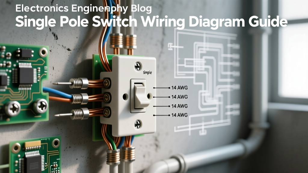
When examining a standard 15-amp switch, such as the widely used Leviton Decora 5601, you will identify three primary terminal points: two brass-colored screws for the hot and load conductors, and one green screw for the equipment grounding conductor. Notably, a standard single pole switch does not utilize a neutral wire connection. The neutral bypasses the switch entirely, traveling directly from the power source to the lighting fixture to complete the 120V AC circuit.
The Core Wiring Diagram: Power at the Switch Box
The most straightforward and common configuration in modern construction is the "Power at the Switch" setup. In this scenario, the main branch circuit from the breaker panel enters the switch box first, and a secondary cable runs from the switch to the light fixture.
Step-by-Step Wiring Logic
- Line (Hot) Conductor: The black wire from the incoming power source (Line) connects to one of the brass terminals on the switch.
- Load Conductor: The black wire of the cable heading up to the light fixture (Load) connects to the second brass terminal. Because a single pole switch simply breaks the circuit, polarity on the brass screws does not matter; either black wire can go on either brass screw.
- Neutral Bypass: The two white (neutral) wires—one from the panel, one to the light—are spliced together using a wire nut or push-in connector (like a Wago 221-412). They do not land on the switch.
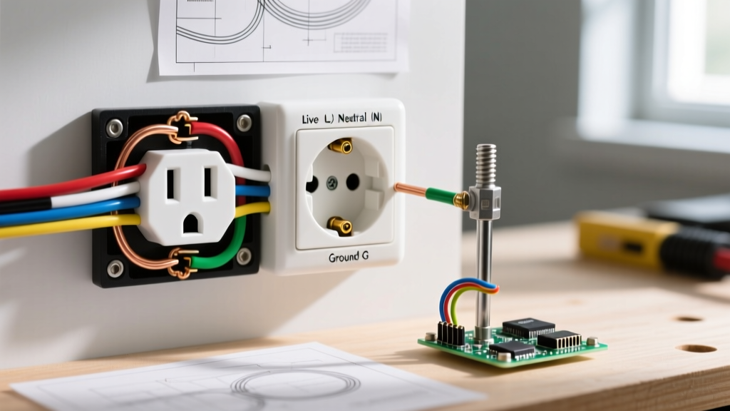
- Grounding: All bare copper or green grounding wires are spliced together and a pigtail is run to the green grounding screw on the switch yoke, as well as to a metal box if applicable.
Alternative Diagram: Power at the Light Fixture (Switch Loop)
In older homes or specific retrofit scenarios, you will encounter a "Power at the Light" configuration, commonly known as a switch loop. Here, the hot and neutral from the breaker panel enter the ceiling fixture box first. A single 2-conductor cable drops down to the switch.
NEC Re-Identification Requirements
Wiring a single pole light switch in a switch loop requires strict adherence to the National Electrical Code (NEC). Because you only have two wires (typically black and white) traveling down to the switch, the white wire must be used as a hot conductor. According to NEC Article 200.7(C), any white conductor used as an ungrounded (hot) conductor must be permanently re-identified. You must wrap the white wire in black electrical tape or use black heat-shrink tubing at both ends to alert future electricians that this wire carries live voltage, not neutral return current.
- At the Fixture: The incoming black (hot) from the panel is spliced to the re-identified white wire dropping to the switch. The incoming white (neutral) connects directly to the light fixture's neutral lead. The black wire returning from the switch connects to the light fixture's hot (black) lead.
- At the Switch: The re-identified white wire (hot) connects to one brass screw. The black wire (switched hot/load) connects to the other brass screw.
The Modern NEC Neutral Requirement at the Switch
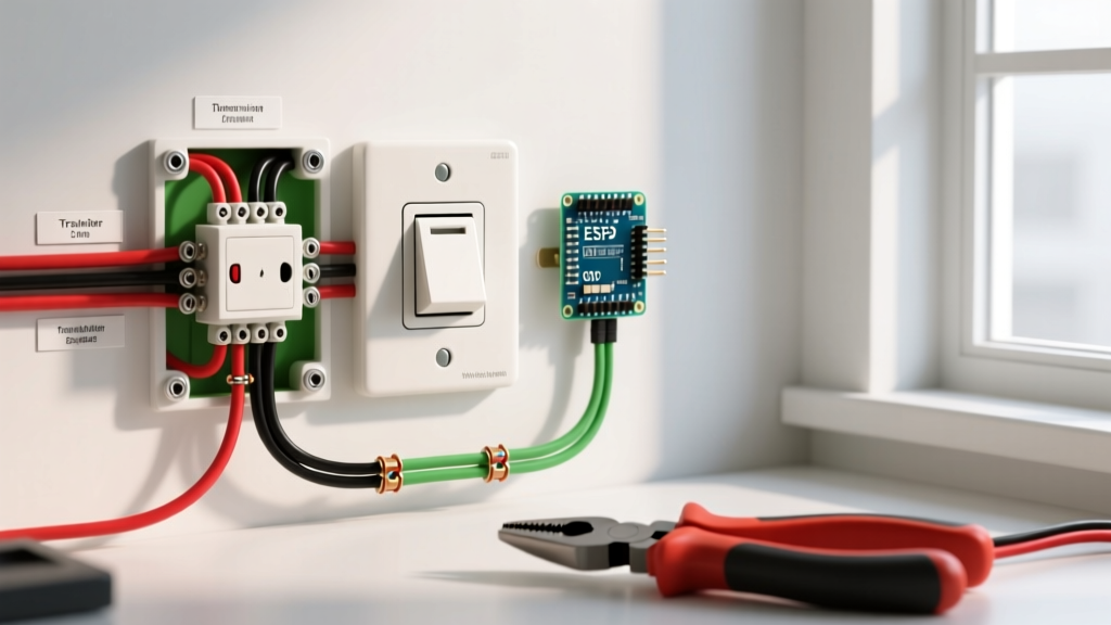
It is critical to note that the NEC now requires a neutral conductor to be present at nearly all switch boxes controlling lighting loads, even if the specific single pole switch installed does not use it. This code update was implemented to accommodate smart switches, timers, and motion sensors that require standby power. Therefore, professional electricians now routinely pull 14/3 or 12/3 NM-B cable for switch loops, capping the unused red or white neutral wire in the back of the box for future use.
Conductor Sizing, Breaker Matching, and Box Fill
When referencing wiring diagrams, you must match the wire gauge to the circuit breaker and ensure the electrical box has adequate volume. Overcrowding a switch box leads to heat buildup and damaged wire insulation.
| Circuit Breaker | Wire Gauge (NM-B) | Max Wattage (120V) | Min. Box Volume (Single Gang) |
|---|---|---|---|
| 15 Amp | 14 AWG | 1,800 Watts | 18.0 Cubic Inches |
| 20 Amp | 12 AWG | 2,400 Watts | 20.25 Cubic Inches |
Per Mike Holt Enterprises' NEC training guidelines and NEC Article 314.16, each conductor entering and terminating in the box counts as one "fill allowance." A standard single pole switch with one incoming and one outgoing 14/2 cable contains four current-carrying conductors, plus grounds and the switch yoke itself. Always verify the cubic inch stamp on the back of the plastic or metal switch box before proceeding.
Termination Techniques: Side-Wiring vs. Back-Wiring
How you physically terminate the wires on the switch yoke drastically impacts the longevity and safety of the installation. There are three primary methods found on modern switches:
1. Side-Wiring (Screw Terminals)
This is the traditional and most reliable method. Using a tool like the Klein Tools 11055 wire strippers, strip exactly 5/8-inch of insulation. Form a tight J-hook using needle-nose pliers and loop it clockwise around the brass screw. As the screw tightens, it pulls the loop closed rather than pushing it out. Ensure no bare copper is exposed outside the screw head, and that no insulation is trapped beneath the washer.
2. Back-Stabbing (Push-In Terminals)
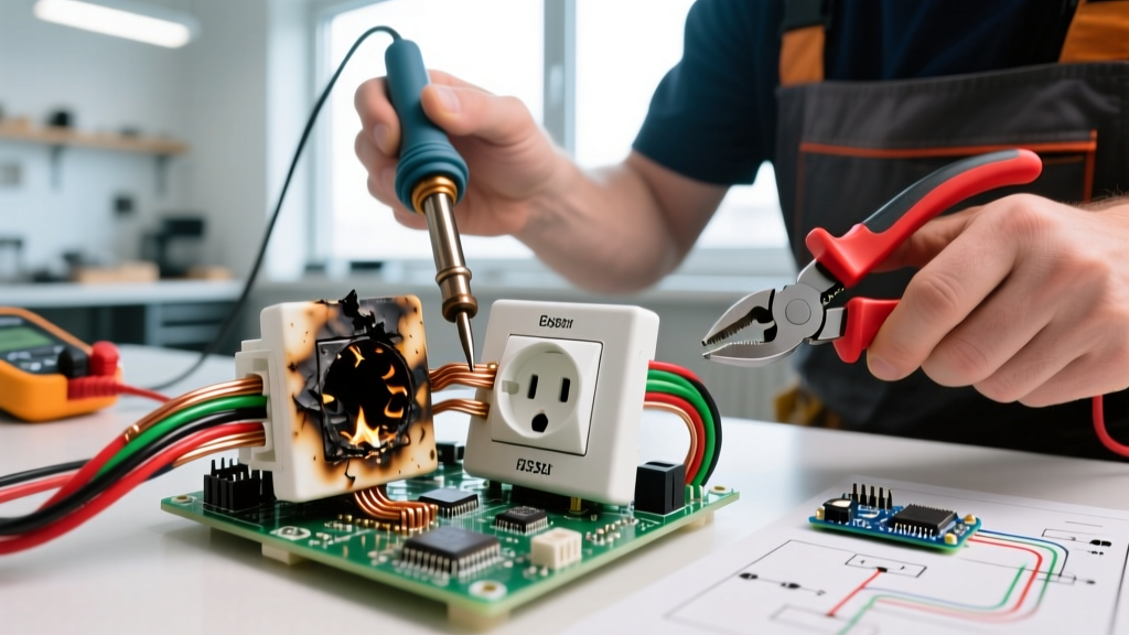
Many budget-grade 15A switches feature small holes on the back for quick push-in connections. Master electricians universally advise against backstabbing. These connections rely on a tiny internal spring-loaded brass wiper. Over time, thermal expansion and contraction from the electrical load cause the spring to fatigue, leading to high-resistance connections, arcing, and ultimately, melted switch housings or electrical fires.
3. Side-Back-Wiring (Clamp Plates)
Higher-end commercial switches (like the Leviton ProGrade series) feature a hybrid system. You insert the straight-stripped wire into a hole on the back, but tightening the side screw clamps a heavy-duty brass plate down onto the wire. This provides the speed of back-wiring with the mechanical security of a screw terminal. When using torque-sensitive commercial devices, referencing a torque screwdriver ensures you meet the manufacturer's exact lb-in specification.
Troubleshooting Common Single Pole Wiring Failures
Even with a correct diagram reference, physical installation errors can occur. Here is how to diagnose specific failure modes:
- Breaker Trips Immediately Upon Energizing: This almost always indicates a dead short. The most common cause in single pole wiring is a ground wire accidentally touching one of the brass terminal screws or the bare ground contacting the hot black wire inside the crowded box. Turn off the power, pull the switch out, and inspect for pinched insulation.
- Light Flickers When the Switch is ON: If the switch is fully toggled to the "ON" position but the light flickers, the issue is rarely the switch itself. It is usually a loose neutral connection at the light fixture or a failing LED driver. However, if you used backstabbed push-in terminals, the internal wiper may be failing under load.
- Switch Yoke Feels Warm to the Touch: A standard single pole switch should never feel warm. Heat indicates high electrical resistance. This happens when the wire gauge is too small for the load (e.g., using 14 AWG wire on a circuit drawing 18 amps), or when the terminal screws were not tightened sufficiently, causing micro-arcing.
Expert Safety Note: Never assume a circuit is dead based solely on the switch position or a non-contact voltage tester. Always verify the absence of voltage at the bare copper ground and the hot terminals using a calibrated multimeter or a solenoid voltage tester (like a Wiggy) before touching any conductors. For comprehensive safety standards regarding residential wiring and arc-fault protection, refer to the Consumer Product Safety Commission (CPSC) guidelines on electrical fire prevention.