To separate ground and neutral in a subpanel, you must install an isolated equipment grounding bar that is not physically bonded to the panel chassis, route all bare copper or green ground wires to this isolated bar, and keep all white or gray neutral wires strictly on the factory-installed neutral bar. The main service panel remains the only location in a standard US residential split-phase system where the neutral and ground are intentionally bonded together. This guidance assumes standard 120/240V copper wiring and follows NEC-style practice; always defer to your local Authority Having Jurisdiction (AHJ) for final code compliance.
The Hazard: What Happens When Ground and Neutral Are Bonded in a Subpanel
If you fail to separate the ground and neutral in a subpanel, you create a parallel path for normal return current. In a properly wired system, the neutral wire carries the unbalanced return current back to the main panel transformer. The equipment grounding conductor (EGC) is a safety shield meant to carry current only during a fault condition (like a hot wire touching a metal appliance chassis) to trip the breaker.
When the neutral and ground are bonded at the subpanel—either by leaving the main bonding screw installed or by landing both wires on the same un-isolated bus bar—the return current splits. A portion of the normal, everyday neutral current will flow back to the main panel along the bare ground wires.
Because ground wires are connected to every metal enclosure, appliance frame, and outlet cover plate downstream of the subpanel, bonding them to the neutral energizes all those metal surfaces with a measurable voltage. If a person touches a grounded appliance and a true earth ground (like a concrete floor or plumbing pipe), they can complete the circuit and receive a shock. Furthermore, this parallel current can cause GFCI breakers to nuisance-trip and can overload undersized ground wires, creating a fire risk. According to the National Fire Protection Association (NFPA), improper grounding and bonding are leading contributors to residential electrical fires and electrocution incidents.
Ground vs. Neutral vs. Bond: Clearing Up the Confusion
Before touching a screwdriver, you must understand the distinct physical and electrical roles of the conductors in your panel. Misidentifying these is the most common cause of subpanel wiring errors.
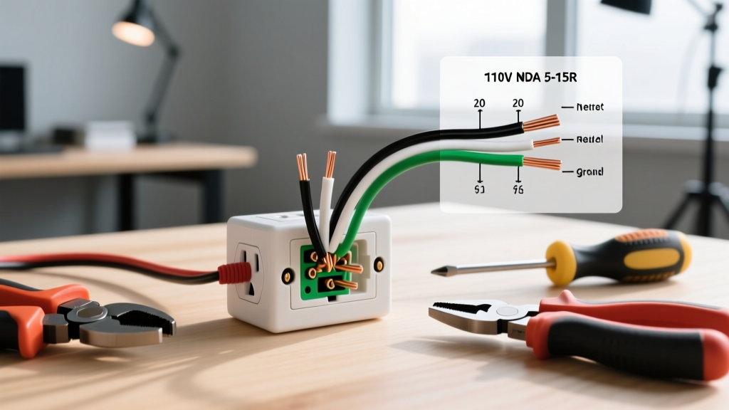
- Neutral (Grounded Conductor): The current-carrying return path for 120V circuits. It is tied to earth ground at the service entrance but carries continuous load current.
- Ground (Equipment Grounding Conductor / EGC): The non-current-carrying safety path. It connects metal parts to the earth to ensure a low-impedance path for fault currents, forcing the breaker to trip instantly.
- Bonding: The intentional physical and electrical connection between the neutral bus and the metal panel enclosure. This is done only at the main service disconnect.
The table below breaks down the exact specifications for these conductors in a standard US residential system.
| Conductor / Component | Primary Function | Standard Wire Color (US) | Carries Normal Load Current? | Where it Terminates in Subpanel |
|---|---|---|---|---|
| Neutral (Grounded Conductor) | Completes the 120V circuit; returns unbalanced current to the source. | White or Gray | Yes, continuously. | Factory-installed Neutral Bar (isolated from chassis) |
| Equipment Ground (EGC) | Provides a low-impedance fault path to trip the breaker during a short. | Bare Copper or Green | No (only during a fault). | Added Ground Bar (physically bonded to chassis) |
| Main Bonding Jumper | Connects the neutral bus to the metal panel enclosure. | Green Screw, Strap, or Wire | No. | Main Panel ONLY (Must be removed in subpanel) |
| Grounding Electrode Conductor (GEC) | Connects the electrical system to physical earth (ground rods, ufer). | Bare Copper (typically #6 to #4 AWG) | No. | Main Panel Neutral/Ground Bus ONLY |
Step-by-Step: How to Separate Ground and Neutral in a Subpanel
Working inside a panel exposes you to lethal mains voltage. The Occupational Safety and Health Administration (OSHA) mandates strict lockout/tagout and verification procedures before any electrical work begins. Never assume a breaker is off just because the handle is flipped.
Turn off the main breaker supplying the subpanel (located in the main service panel). Use a non-contact voltage tester (NCVT) to check all wires in the subpanel. Then, use a digital multimeter (DMM) rated CAT III or CAT IV to verify 0V between the hot bus bars, and between the hot bus bars and the neutral/ground. Test your meter on a known live source before and after to ensure the battery isn't dead.
1. Remove the Main Bonding Jumper
Many subpanels ship from the factory with a green bonding screw or a metal bonding strap pre-installed to accommodate use as a main panel. Locate this green screw (usually on the neutral bar, threading directly into the metal backplane of the panel). Remove it completely. If your panel uses a bonding strap or wire, cut it or unbolt it. Keep the screw in a baggy taped to the inside of the panel door so the next electrician knows it was intentionally removed.
2. Install an Isolated Equipment Grounding Bar
If your subpanel does not have a separate ground bar, you must buy an accessory ground bar kit matched to your panel brand (e.g., Square D HOM, Eaton BR, Siemens). These kits cost between $8 and $15. Mount the ground bar directly to the metal panel chassis using the pre-tapped holes in the backplane. Because it mounts directly to the metal, it is inherently bonded to the chassis—which is exactly what you want for the ground path.
3. Land the Conductors Correctly
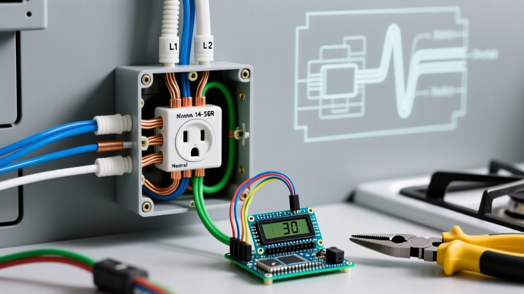
- Neutrals (White/Gray): Land all neutral wires, including the large white feeder neutral from the main panel, exclusively on the factory-installed neutral bar. Ensure the neutral bar is floating (not touching the metal chassis).
- Grounds (Bare/Green): Land all equipment grounding wires, including the feeder ground from the main panel, exclusively on the newly installed accessory ground bar.
- Hots (Black/Red/Blue): Land on the hot bus stabs. Ensure the feeder breaker in the main panel matches the subpanel's ampacity rating.
4. Torque to Specification
Modern NEC-style guidelines (specifically NEC 110.14(D)) require the use of a calibrated torque screwdriver for panel terminations. Hand-tightening leads to loose connections that arc and cause fires. For standard #12 to #10 AWG copper conductors, the typical torque spec is 20 to 25 inch-pounds. Check the label inside your specific panel door for the exact manufacturer torque requirements.
5. Verify the Separation with a Tester
Once power is restored, you must verify the separation is working correctly without opening the panel again.
- Go to the furthest downstream receptacle fed by the subpanel.
- Plug in a heavy load (like a hair dryer or space heater) to draw at least 10 amps.
- Using a DMM, measure the voltage between Hot and Neutral. Note the reading (e.g., 116V).
- Measure the voltage between Hot and Ground. It should be nearly identical to Hot-Neutral.
- Measure the voltage between Neutral and Ground. Under load, this should read between 0.5V and 2.0V (representing the voltage drop on the neutral wire).
- If it reads 0.0V exactly: You likely have an illegal neutral-to-ground bond somewhere downstream, or the subpanel bond was not removed.
- If it reads 120V: You have an open neutral (broken or disconnected white wire), which is an immediate emergency.
When to Call a Licensed Electrician
While separating ground and neutral in an existing, properly fed subpanel is a straightforward task for a competent DIYer, certain scenarios strictly require a licensed electrician. You must hire a professional if:
- You are installing a new feeder: Sizing the feeder cable (e.g., 2-2-2-4 Aluminum MHF for a 100A subpanel), calculating voltage drop over long distances, and terminating the new breaker in the main service panel involves complex ampacity derating and mains-side exposure.
- The main panel lacks capacity: If your main service panel is maxed out on bus bar ampacity or physical spaces, adding a subpanel feeder requires a service upgrade or a line-side tap, which is utility-level work.
- You are dealing with a 3-wire feeder: Older homes (pre-2008 NEC) sometimes used 3-wire feeders (Hot-Hot-Neutral) to subpanels, relying on the neutral for both return and ground. Upgrading this to a modern 4-wire system (Hot-Hot-Neutral-Ground) requires pulling new wire through walls.
- Local AHJ mandates it: Many municipalities legally restrict any work inside the main service panel or the installation of new subpanels to licensed, bonded contractors. Always pull the required permits and schedule the rough/final inspections.
By maintaining a strict physical separation between the current-carrying neutral and the safety-focused ground at the subpanel, you ensure that metal enclosures remain at zero potential during normal operation, while still providing a robust, low-impedance path to trip the breaker the millisecond a fault occurs.