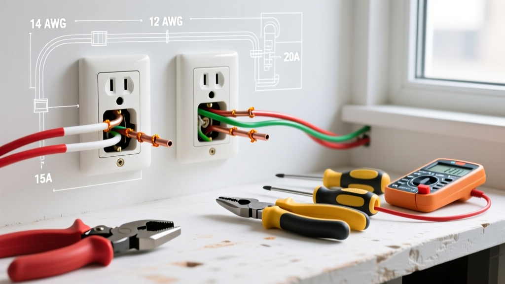
When performing Legrand socket outlet rating checking on an existing wall box or planning a new branch circuit, the direct answer is simple: match the receptacle ampacity to the circuit breaker and wire gauge. A 15-amp Legrand receptacle (like the 5262-F) requires a 15A breaker and 14 AWG copper wire. A 20-amp Legrand receptacle (like the 5362-F) requires a 20A breaker and 12 AWG copper wire. You can identify the rating by checking the yoke stamping or looking at the faceplate slots—a 20A outlet features a distinct T-shaped neutral slot.
This guide walks through the exact decision framework for selecting the right Legrand Pass & Seymour device, the step-by-step termination procedure with specific wire colors, and the meter readings you need to verify a safe, code-compliant installation.
The Decision Path: Sizing Your Legrand Receptacle
Before you strip a single wire, you must determine what the circuit can handle. The National Electrical Code (NEC) strictly governs how receptacles are matched to branch circuits. While NFPA 70 (NEC) Article 210.21(B)(3) allows 15A receptacles on 20A circuits under specific multi-outlet conditions, best practice for DIY and residential upgrades is a direct 1:1 match for maximum durability and safety.
| Breaker Size | Wire Gauge (Copper) | Legrand Part Number | Device Rating | Faceplate Slot Shape |
|---|---|---|---|---|
| 15 Amp | 14 AWG | 5262-F (Spec Grade) | 15A / 125V | Two straight vertical slots |
| 20 Amp | 12 AWG | 5362-F (Spec Grade) | 20A / 125V | T-shaped neutral slot |
The Concrete Pick: If you are wiring a standard 120V kitchen, garage, or bathroom circuit with 12 AWG NM-B cable and a 20A breaker, buy the Legrand Pass & Seymour 5362-F 20A Spec Grade receptacle. The 'F' denotes the tamper-resistant (TR) mechanism required by modern code for residential dwellings, and the Spec Grade internal contacts provide superior clamping force compared to residential-grade builder packs.
Tools, Materials, and Mains Safety Protocol
Working with 120V AC branch circuits requires strict adherence to safety protocols. Arc flashes and fatal shocks occur when testers are bypassed or assumptions are made about wire coloring.
Required Tools and Materials
- Device: Legrand Pass & Seymour 5362-F (20A) or 5262-F (15A) Tamper-Resistant Receptacle
- Wire: 12/2 NM-B (Romex) for 20A circuits, or 14/2 NM-B for 15A circuits
- Strippers: Klein Tools 11055 (10-18 AWG) or equivalent automatic wire strippers
- Multimeter: Fluke 117 True-RMS Multimeter (or equivalent CAT III rated meter)
- Tester: NCVT (e.g., Fluke 1AC-II) and a standard 3-light receptacle tester
- Screwdriver: #2 Phillips and a Wiha torque screwdriver (calibrated to 14 in-lbs)
Step-by-Step Wiring: Termination and Wire Colors
Proper termination ensures low contact resistance, which prevents voltage drop and thermal runaway under heavy loads (like a 1500W space heater drawing 12.5A). Always use the side-binding screw terminals on Legrand Spec Grade devices, not the push-in backwire holes.
- Prepare the Box and Wires: Ensure the electrical box is clear of debris. Strip exactly 5/8 inch of insulation from the 12 AWG or 14 AWG THHN/NM-B conductors using your wire strippers. Do not nick the copper; a nicked wire creates a weak point that can snap under torque.
- Form the J-Hook: Using the loop hole on your wire strippers, bend the bare copper ends into a tight 'J' hook. The radius of the hook should perfectly match the radius of the terminal screw on the Legrand receptacle.
- Terminate the Ground (Bare/Green): Wrap the bare copper (or green THHN) grounding conductor clockwise around the Green terminal screw at the bottom of the yoke. Tighten securely. The clockwise wrap ensures the screw pulls the wire tighter as it turns.
- Terminate the Neutral (White): Wrap the white insulated neutral wire clockwise around one of the Silver terminal screws on the left side of the yoke. Ensure no bare copper is exposed outside the terminal plate, and no insulation is trapped under the screw head.
- Terminate the Hot (Black): Wrap the black insulated hot wire clockwise around one of the Brass terminal screws on the right side of the yoke.
- Apply Final Torque: Tighten all three terminal screws to the manufacturer's specification. For Legrand Pass & Seymour spec grade receptacles, the target torque is typically 14 in-lbs. If you lack a torque screwdriver, tighten until the screw is snug and the wire cannot be pulled free with a firm tug, but do not overtighten to the point of stripping the brass threads.
- Check the Break-Off Fin: Look at the brass side of the yoke between the top and bottom brass screws. There is a small metal connecting fin. For a standard single-circuit outlet, leave this fin intact. Only break it off with needle-nose pliers if you are intentionally split-wiring the top and bottom halves on separate breakers (a multi-wire branch circuit).
Verification and Testing: Expected Meter Readings
Do not push the receptacle into the box and screw on the faceplate until you have verified the electrical parameters. Pushing a miswired device into a crowded box can cause a short circuit when the breaker is energized.
- Energize the Circuit: Return to the panel and flip the breaker fully to the ON position.
- Test Voltage (Hot to Neutral): Set your Fluke 117 to AC Voltage (V~). Insert the black probe into the shorter slot (Hot/Brass) and the red probe into the longer slot (Neutral/Silver).
Expected Reading: 114V to 126V AC. (120V nominal). If you read 0V, the breaker is off or a wire is disconnected. If you read 240V, you have a severe wiring fault (two hots on a 120V circuit). - Test Voltage (Hot to Ground): Insert the black probe into the Hot slot and the red probe into the D-shaped Ground hole.
Expected Reading: 114V to 126V AC. This confirms the equipment grounding conductor is bonded back to the panel. - Test Voltage (Neutral to Ground): Insert probes into the Neutral slot and Ground hole.
Expected Reading: 0V to 2V AC. A reading higher than 3V indicates a loose neutral connection somewhere upstream or an overloaded shared neutral. - Verify with a 3-Light Tester: Plug a standard receptacle tester into the top and bottom sockets. You should see two yellow lights illuminated (Correct Wiring). If you see a red light, you have reversed hot and ground or hot and neutral.
The Most Common Botch: Backstabbing and Thermal Failure
The single most frequent mistake made by DIYers and rushed contractors when installing Legrand (or any brand) receptacles is using the push-in backwire holes instead of the side-binding screw terminals. This practice, known as 'backstabbing', relies on a tiny internal leaf spring to bite into the copper wire.
The Symptom: The circuit works fine for low-draw devices like phone chargers. However, when you plug in a 12A hair dryer or a 1500W space heater, the outlet begins to buzz, the plastic faceplate warms up, and eventually, the power to downstream outlets cuts out intermittently. In severe cases, the internal spring loses its temper due to heat, leading to arcing, melted plastic, and a burn mark on the yoke.
The Fix: Always use the side-binding screws. If you must use backwiring for speed in a commercial setting, use Legrand devices that feature back-clamp terminals (where the screw tightens a solid brass plate against the wire), not push-in spring clips. For standard residential 5262-F and 5362-F models, the side screws are the only reliable termination method. Furthermore, ensure you are using solid copper wire for push-in connections; stranded wire will fray and fail in a push-in terminal, violating OSHA and NEC safety standards for secure connections.
By strictly following the wire-to-terminal color mapping, torquing the side screws to 14 in-lbs, and verifying your 120V readings with a True-RMS meter, your Legrand socket outlet installation will provide decades of safe, reliable service without the risk of thermal degradation.