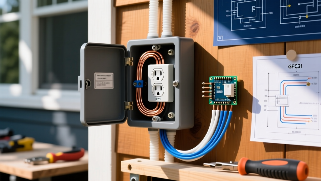

Mastering the Basics: How to Install an Electrical Outlet
Replacing or installing a standard 15-amp, 120-volt duplex receptacle is one of the most fundamental skills in residential electrical work. Whether you are finishing a basement, upgrading a damaged wall plate, or adding a new drop to an existing circuit, understanding how to install an electrical outlet correctly ensures both functionality and safety. In 2026, modern electrical codes are stricter than ever, emphasizing tamper resistance and precise torque specifications. This beginner installation tutorial will walk you through the exact process of wiring a standard 15A outlet, using professional-grade techniques that prevent the most common DIY failures, such as backstabbed connections and reversed polarity.
Understanding the 2026 NEC Landscape
Before picking up a screwdriver, you must understand the current National Electrical Code (NEC) requirements that govern residential receptacles. The most critical rule for beginners is NEC 406.12, which mandates that all 15A and 20A, 125V and 250V receptacles installed in dwelling units must be Tamper-Resistant (TR). TR receptacles feature internal spring-loaded shutters that prevent children from inserting foreign objects into the slots. According to the Consumer Product Safety Commission (CPSC), TR receptacles have drastically reduced childhood electrocution incidents since their widespread adoption. Furthermore, the NEC continues to tighten rules around termination torque (NEC 110.14(D)), meaning 'hand-tight' is no longer the professional standard; specific inch-pound torque ratings are now expected for long-term reliability.
Essential Tools & Materials Matrix
To execute this installation properly, you need more than just a basic flathead screwdriver. Below is a matrix of the specific tools and materials required for a professional-grade 15A outlet installation, along with current 2026 pricing estimates.
| Item Category | Specific Model / Type | Purpose | Est. Cost |
|---|---|---|---|
| Receptacle | Leviton 15A TR Duplex (R52-05320-00W) | Code-compliant, tamper-resistant outlet | $1.80 - $2.50 |
| Wire Strippers | Klein Tools 11055 (14-16 AWG) | Precision stripping without nicking copper | $25.00 |
| Voltage Tester | Fluke 1AC-II Non-Contact VoltAlert | Verifying dead circuit before touching wires | $35.00 |
| Screwdriver | Milwaukee 48-22-2601 Phillips #2 | Securing terminal screws without cam-out | $8.00 |
| Torque Tool | IDEAL 33-090 Torque Screwdriver | Applying exact 14 in-lbs to terminals | $45.00 |
| Wire Connectors | Ideal Wire-Nut (Yellow #452) | Pigtailing ground or neutral if needed | $0.15 each |
Step 1: Kill the Power and Verify
The most dangerous mistake a beginner can make is assuming a wall switch or a labeled breaker has actually killed the power to the outlet. Always verify the circuit is dead at the point of work.
- Locate the Breaker: Go to your main electrical panel and switch off the breaker controlling the room. If the panel is poorly labeled, use a radio or lamp plugged into the outlet to confirm when the power drops.
- Test with a Non-Contact Voltage Tester: Insert the tip of your Fluke 1AC-II into both the top and bottom slots of the existing outlet. The tester should remain completely dark and silent. If it glows red or beeps, the power is still on. Never proceed if you detect voltage.
- Remove the Faceplate and Receptacle: Unscrew the decorative cover plate, then remove the two long machine screws holding the receptacle yoke to the electrical box. Gently pull the outlet out to expose the wiring.
Step 2: Cable Preparation and Stripping
Proper wire preparation is the secret to a secure connection that won't arc or overheat over time. Most residential 15A circuits use 14 AWG NM-B (Romex) cable, though 12 AWG is also common and perfectly acceptable on a 15A breaker.
- Strip the Outer Sheathing: If you are running new cable into the box, use a cable ripper or utility knife to remove exactly 3/4 of an inch of the outer PVC jacket inside the box. Do not nick the inner insulation of the individual conductors.
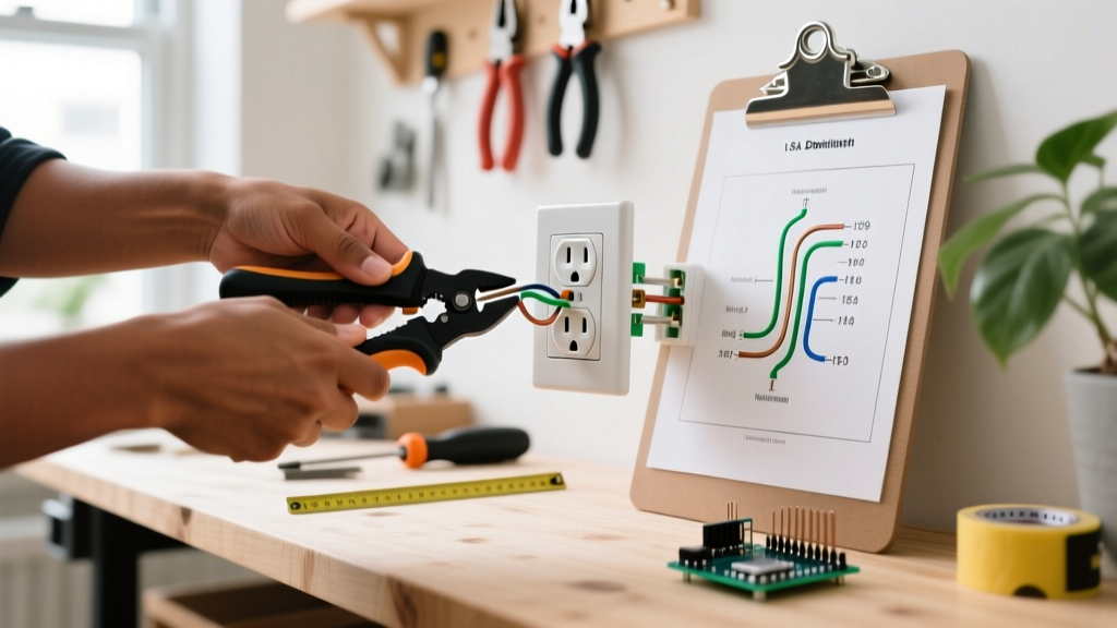
- Strip the Conductors: Using your Klein Tools 11055 wire strippers, strip exactly 1/2 inch to 5/8 inch of insulation from the black (hot), white (neutral), and bare copper (ground) wires. Stripping too little leaves exposed copper outside the terminal; stripping too much exposes bare wire near the screw head, creating a shock hazard.
- Form the J-Hook: Use the needle-nose pliers built into your wire strippers to bend the exposed copper into a smooth, 180-degree 'J-hook'. This hook must be perfectly shaped to wrap around the terminal screw.
Step 3: Termination Methods (Side-Wire vs. Back-Wire)
When learning how to install an electrical outlet, you will notice three ways to connect wires to the Leviton R52-05320-00W receptacle. Choosing the right method is critical for safety.
1. Push-In Backstabbing (Avoid Completely)
Many cheap receptacles feature small holes on the back where you can simply push a stripped wire in without using a screw. Never use this method. Backstabbed connections rely on a tiny internal spring clip that grips the wire. Over time, thermal expansion and contraction cause these clips to loosen, leading to high-resistance connections, arcing, and electrical fires.
2. Side-Wiring (The Standard Method)
This is the most common DIY method. Hook your J-hooked wire around the terminal screw in a clockwise direction. When you tighten the screw clockwise, the hook will close tightly around the screw shaft rather than being pushed out. Ensure no bare copper is visible outside the terminal plate, and no insulation is trapped under the plate.
3. Screw-and-Clamp Back-Wiring (The Professional Choice)
Higher-end commercial and residential receptacles feature a 'back-wire' clamp system. You insert the straight, stripped wire into the back hole and tighten the screw, which pulls a heavy-duty brass clamp down onto the wire. This provides maximum surface area contact and is highly resistant to pull-out.
Pro-Tip for 2026 Code Compliance: The NEC and UL listings increasingly emphasize proper torque. While a standard Phillips screwdriver feels 'tight', professional electricians use a torque screwdriver set to the manufacturer's specification—typically 14 in-lbs for standard 15A receptacle terminal screws. This prevents both under-tightening (causing arcing) and over-tightening (stripping the brass threads).
Step 4: Securing, Folding, and Testing
Once the black wire is on the brass (hot) screw, the white wire is on the silver (neutral) screw, and the bare copper is on the green (ground) screw, it is time to secure the device.
- Fold the Wires: Gently fold the wires in a Z-pattern into the back of the electrical box. Do not just jam them in, as crushing the wires against the back of the receptacle can damage the insulation or push a wire off a terminal.
- Mount the Receptacle: Align the yoke with the box and drive the two 6-32 mounting screws. Use a level to ensure the outlet is perfectly plumb before fully tightening.
- Test Before Powering: Plug a Klein Tools RT210 Receptacle Tester into the top and bottom sockets. Turn the breaker back on at the panel. The RT210 uses a specific LED light pattern to verify correct wiring. Two yellow lights mean 'Correct'. A red light indicates reversed polarity (hot and neutral swapped), while a single yellow light indicates an open ground.
Troubleshooting Common Edge Cases
Even with careful installation, beginners may encounter specific failure modes during testing. Here is how to address them:
- Open Neutral (One light on tester): The white wire is not making solid contact at the silver screw, or a wire nut upstream has failed. Turn the power back off and check the terminal clamp.
- Hot/Ground Reverse (Red and Yellow lights): This is a dangerous condition usually caused by accidentally connecting the black hot wire to the green ground screw. This will energize the entire grounding system of the house. Immediately kill power and re-terminate.
- GFCI Tripping Upstream: If this outlet is fed from a GFCI receptacle in another room (like a bathroom or garage) and the GFCI trips when you plug in a load, you may have crossed the neutral wires or connected the new outlet to the 'LOAD' side of a multi-wire branch circuit incorrectly.
Frequently Asked Questions
Can I install a 15A receptacle on a 20A breaker?
Yes, under NEC 210.21(B)(3), you are permitted to install multiple 15A duplex receptacles on a single 20A circuit, provided there is more than one receptacle on the circuit. However, you cannot install a single 15A receptacle as the only outlet on a 20A circuit. Furthermore, you must use 12 AWG wire for the entire 20A circuit; never use 14 AWG wire on a 20A breaker, as this violates NEC 240.4(D) and creates a severe fire hazard.
Do I need to replace my old, non-TR outlets?
The NEC is generally not retroactive. You are not legally required to replace existing, functioning non-Tamper-Resistant outlets in an older home. However, the moment you replace a broken outlet or add a new one, the 2026 NEC requires the new installation to be TR compliant. Given that TR receptacles like the Leviton R52-05320-00W cost less than $2.00, upgrading them proactively is a highly recommended safety investment for homes with young children.
Why are the terminal screws brass and silver?
The brass screw is for the 'hot' conductor (black or red wire), which carries the 120V from the panel. The silver screw is for the 'neutral' conductor (white wire), which completes the circuit back to the panel. The green screw is exclusively for the equipment grounding conductor. Mixing these up will result in reversed polarity or energized appliance chassis, which violates OSHA electrical safety standards and poses a lethal shock risk.
By following this structured, code-compliant approach, you ensure your new electrical outlet is not only functional but built to last decades without thermal degradation. For more advanced wiring scenarios, consult the full NFPA National Electrical Code documentation or hire a licensed electrician.