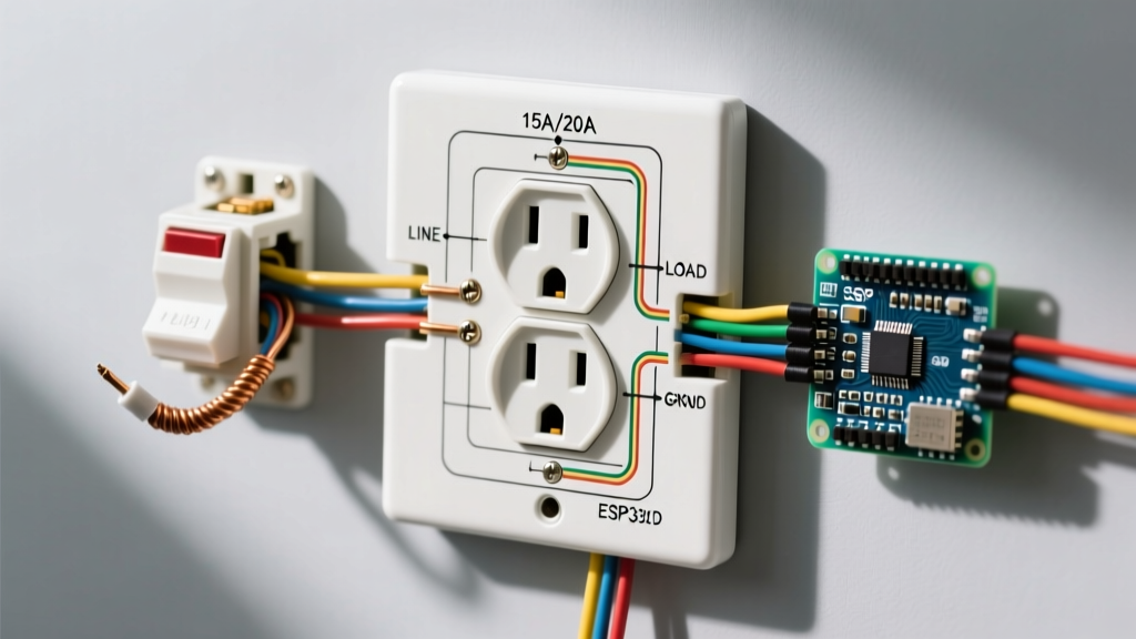
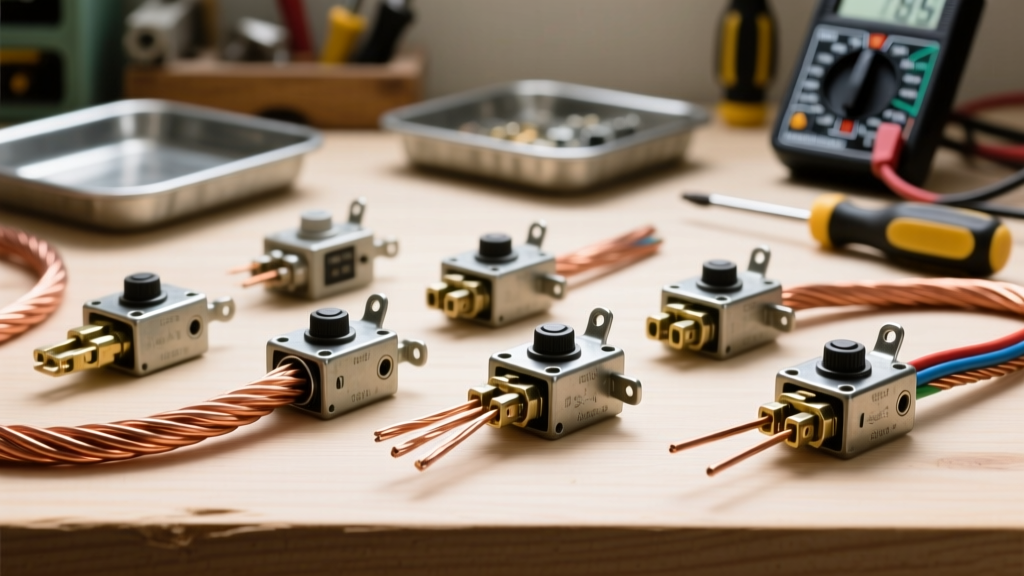
When you open an inductor switch—such as a 240V HVAC contactor, a 120V well pump relay, or a hardwired garage door opener solenoid—the collapsing magnetic field generates a massive high-voltage spike. This inductive kickback arcs across the opening switch contacts, causing pitting, carbon tracking, and eventual contact welding. The direct fix is to install an RC snubber network (typically a 0.1µF X2 film capacitor in series with a 100Ω carbon composition resistor) directly across the inductor coil or the switch contacts to absorb the transient energy.
In home electrical panels and appliance control boards, ignoring inductor switch protection leads to premature relay failure, tripped breakers, and burnt control wiring. This guide breaks down the exact passive components required to tame inductive kickback, how to read their physical markings, and how to safely substitute parts when the exact OEM component is unavailable.
The Physics of the Inductor Switch Kickback
Inductors resist changes in current. When a switch controlling an inductive load (like a motor winding or transformer primary) opens, the current attempts to drop to zero instantly. According to the formula V = -L(di/dt), a massive rate of current change (di/dt) across a large inductance (L) generates a proportionally massive voltage spike (V).
Think of it like water hammer in home plumbing: slamming a valve shut on a fast-moving column of water creates a pressure shockwave that can rupture pipes. In an electrical circuit, that shockwave is a voltage spike that can easily exceed 1,000V on a standard 24V AC HVAC contactor coil. Without a path to dissipate this energy, the voltage will ionize the air gap across the opening switch contacts, creating a plasma arc that melts the metal.
Working inside home electrical panels, HVAC disconnects, or well pump controllers involves lethal mains voltage (120V/240V AC). Always de-energize the circuit at the main breaker, apply a lockout/tagout device, and verify the circuit is dead using a tested CAT III or CAT IV multimeter (like a Fluke 87V) before touching any inductor switch terminals. NEC-style guidance requires proper enclosure and grounding; your local AHJ has final authority on panel modifications.
Passive Component Selection for Snubber Networks
Not all resistors and capacitors can handle the violent transient environment of an inductor switch. Standard components will fail catastrophically. Below is the selection matrix for passives used in AC and DC inductive load suppression.
| Component Type | Construction & Dielectric | Tolerance | Tempco / Drift | Typical Home Electrical Use |
|---|---|---|---|---|
| X2 Metallized Polypropylene Film Cap | Self-healing film, flame-retardant epoxy | ±10% (K) | -200 ppm/°C | AC contactor coils (24V/120V/240V), sump pump relays |
| Metal Oxide Varistor (MOV) | Sintered zinc oxide grains, epoxy coated | ±10% clamping V | Non-linear (degrades with heat/cycles) | High-energy transient clamping across mains switch contacts |
| Carbon Composition Resistor | Solid carbon/clay matrix, non-inductive | ±5% to ±20% | -500 ppm/°C | Snubber damping resistor (limits cap discharge current) |
| Flyback Diode (e.g., 1N4007) | Silicon PN junction, epoxy DO-41 package | N/A (Vf ~1V) | -2mV/°C forward voltage | DC solenoid valves, 12V/24V DC irrigation relays |
Which Type for Which Job?
- For AC Coils (HVAC, Well Pumps): Use an RC snubber (X2 capacitor + Carbon Comp resistor). The capacitor absorbs the spike, and the resistor prevents a massive inrush current from destroying the switch contacts when they close.
- For DC Coils (Irrigation, Smart Home Relays): Use a flyback diode wired in reverse-bias across the coil. It provides a recirculation path for the collapsing magnetic field.
- For High-Energy Mains Switching: Use an MOV across the switch contacts to clamp extreme lightning or grid-switching transients that exceed the RC snubber's energy rating.
Decoding Physical Markings and Substitution Rules
When replacing a burnt snubber on an HVAC control board or sourcing parts for a custom well pump controller, you must read the physical markings accurately. Misinterpreting these codes is the leading cause of repeat failures.
Reading X2 Capacitor Markings
A typical X2 capacitor will read: X2 MKP 0.1µF K 275V~
- X2: Safety certification class. X2 caps are designed to fail open (not short) across the line, preventing fire and shock hazards.
- MKP: Metallized Polypropylene. The required dielectric for high-pulse, self-healing applications.
- 0.1µF: Nominal capacitance.
- K: Tolerance code (K = ±10%, M = ±20%, J = ±5%).
- 275V~: The tilde (~) indicates AC RMS voltage rating. Never substitute a DC-rated capacitor here.
Reading MOV Markings
An MOV might read: 14D471K
- 14: Disc diameter in millimeters (determines energy absorption in Joules).
- D: Package type (D = circular disc).
- 471: Voltage code. First two digits are significant figures (47), third is multiplier (10^1). 47 × 10 = 470V DC clamping voltage.
- K: Tolerance (±10%).
How to Substitute Safely
If the exact OEM snubber is missing, follow these strict substitution rules:
- Never substitute an X2 cap with a Y5V ceramic or electrolytic capacitor. Ceramics exhibit severe voltage coefficient (losing capacitance under high voltage) and fail as dead shorts, which will blow your control fuse or start a fire.
- Never use a wirewound resistor for the snubber damping element. Wirewound resistors are literally coils of wire; they possess their own inductance, which defeats the purpose of the snubber and can cause high-frequency ringing. Always use carbon composition or metal film.
- Voltage uprating is safe; capacitance uprating is risky. You can safely substitute a 305V~ X2 cap for a 275V~ cap. However, increasing the capacitance (e.g., from 0.1µF to 0.47µF) increases the steady-state AC leakage current and the inrush current when the inductor switch closes, potentially welding the contacts.
Failure Modes and Visual Symptoms
Passive components in inductor switch circuits operate in a harsh environment. Recognizing their failure modes during preventative maintenance saves hours of troubleshooting.
1. X2 Capacitor Degradation (Capacitance Loss)
The Physics: Over years of absorbing micro-arcs and voltage spikes, the self-healing metallization inside the film capacitor vaporizes in tiny zones, gradually reducing the total surface area and thus the capacitance.
Visual Symptom: No external bulging or scorching. The cap looks pristine.
Diagnostic: Desolder one leg and measure with a multimeter's capacitance setting. If a 0.1µF cap reads below 0.07µF, it is exhausted. The resulting symptom will be pitted, blackened contactor points.
2. MOV Thermal Runaway and Shattering
The Physics: MOVs degrade with each transient absorption event. If subjected to a sustained overvoltage (like a lost neutral on a 120/240V split-phase system), the MOV absorbs continuous power, overheats, and fails short.
Visual Symptom: The epoxy coating is cracked, blistered, or completely blown off, exposing the raw zinc oxide disc. The surrounding PCB or plastic relay housing will show heat melt marks.
Diagnostic: Visual inspection. If an MOV has failed short, it will typically trip the upstream branch breaker.
3. Carbon Composition Resistor Fracture
The Physics: If the snubber capacitor fails short, the full line voltage is dumped through the damping resistor, exceeding its continuous wattage rating (usually 1/2W or 1W).
Visual Symptom: The resistor body is scorched black, the paint is bubbled, or the component has physically cracked in half.
Diagnostic: Measure resistance across the component. An open reading (OL) confirms failure. Always check the series capacitor when replacing a burnt snubber resistor.
Wiring the Inductor Switch Snubber in Home Panels
When retrofitting an RC snubber to protect a hardwired inductor switch (like a 120V sump pump relay or a 24V AC HVAC contactor), placement is critical.
- Identify the Coil Terminals: Locate the two terminals that energize the inductor (the A1 and A2 terminals on an IEC contactor, or the coil spades on a definite-purpose HVAC contactor).
- Prep the Snubber: If building an RC snubber, solder the 100Ω resistor in series with the 0.1µF X2 capacitor. Cover the bare solder joint with 18AWG heat shrink tubing rated for 600V.
- Mounting Location: The snubber must be placed as close to the inductor coil as physically possible. If you place it across the switch contacts at the thermostat instead of the contactor coil at the condenser, the wiring inductance between the switch and the coil will still cause arcing at the switch.
- Termination: Crimp a #10 or #12 AWG ring terminal or spade connector onto the snubber leads. Slide the spade connector under the existing coil terminal screw alongside the control wire. Torque the terminal to the manufacturer's spec (typically 12-15 in-lbs for small contactors) to prevent vibration loosening.
- Verify: Re-energize the circuit. Use an oscilloscope or a True-RMS multimeter with a min/max peak-hold function (like the Fluke 87V) across the coil. When the switch opens, the transient voltage should clamp safely below the insulation rating of the coil wire (usually <600V for standard magnet wire).
For deeper theoretical analysis on snubber design equations and damping factors, the All About Circuits guide on snubber circuits provides excellent mathematical modeling. Additionally, when selecting specific safety-rated capacitors for mains-adjacent home wiring, cross-reference the component datasheets with the Components101 X2 Capacitor breakdown to ensure your dielectric selection meets IEC 60384-14 safety standards.
By correctly sizing and placing these passive components, you eliminate the destructive arcing that destroys home electrical switches, extending the life of your contactors and relays from a few thousand cycles to well over a million.