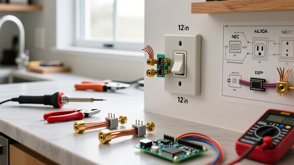
If a 120V hot wire frays inside the metal casing of your refrigerator or drill press, the chassis becomes energized. Without a proper equipment ground, the metal case sits at 120V, waiting for you to touch it and complete the circuit to the earth. The result is a severe or fatal electric shock. With a proper ground, that fault current takes a low-impedance path back to the panel, instantly tripping the breaker before you even reach for the door handle. Understanding how this system works is the difference between a safe workshop and a lethal one.
The Hazard: What Happens When the Ground Fails
The primary hazard that a grounding system prevents is electrocution from energized enclosures and electrical fires from arcing faults. When a hot conductor contacts a metal appliance case, it creates a ground fault. For a standard 20A breaker to trip in under 0.05 seconds (the threshold to prevent ventricular fibrillation), it requires a massive surge of current—often 100A to 200A of instantaneous fault current. This is only possible if the OSHA-recognized equipment grounding conductor (EGC) provides a path of extremely low impedance back to the source. If the ground path is compromised—say, by a rusty pipe clamp, a missing bonding screw, or a reliance on high-resistance dirt—the impedance spikes. The fault current drops to maybe 15A. The 20A breaker sees this as a normal load and refuses to trip. The metal enclosure remains energized at 120V indefinitely. When you touch it, your body (which has an impedance of roughly 1,000 ohms when wet) becomes the parallel path to ground, resulting in a lethal shock.
Ground vs. Neutral vs. Bond: The Core Distinctions
The most common point of confusion for DIYers is treating 'ground', 'neutral', and 'bond' as synonyms. They are fundamentally different systems with different jobs. Here is the exact breakdown of how they function in a standard North American split-phase system.
| Term / Conductor | Primary Role | Carries Normal Current? | Carries Fault Current? | Standard Color Code |
|---|---|---|---|---|
| Neutral (Grounded Conductor) | Completes the 120V circuit; carries return current to the transformer. | Yes (100% of the time) | No | White or Gray |
| Equipment Ground (EGC) | Provides a low-impedance fault path back to the panel to trip the breaker. | No (Never) | Yes (Only during a fault) | Bare Copper or Green |
| Grounding Electrode (GEC) | Connects the panel to the earth (ground rod/water pipe) to stabilize voltage from lightning/surges. | No | Only for high-voltage surges | Bare Copper |
| Bonding | Equipotential bonding: physically connecting all non-current-carrying metal parts together so they sit at the same voltage potential. | No | Yes (Routes fault current) | N/A (Mechanical connection) |
A critical mistake is bonding the neutral and ground bars together in a subpanel. They must only be bonded at the main service disconnect. If you bond them in a subpanel, normal neutral return current will split and flow back through the grounding wires, energizing the metal chassis of every appliance on that subpanel with a few volts of potential.
Sizing the Grounding Electrode Conductor (GEC)
The wire that connects your main panel to the ground rod or metal water pipe (the GEC) is sized based on the largest ungrounded service entrance conductor, not the breaker size. Below is an excerpt of standard NEC-style guidance (Table 250.66) for copper conductors.
| Largest Service Entrance Conductor (Copper) | Minimum Grounding Electrode Conductor (GEC) Size (Copper) |
|---|---|
| #2 AWG or smaller | #8 AWG |
| #1/0 AWG | #6 AWG |
| #250 kcmil | #2 AWG |
| #500 kcmil | #1/0 AWG |
Note: Always consult the latest NFPA National Electrical Code (NEC) for complete tables, as local amendments and aluminum conductor equivalents will alter these values.
How to Verify Your Grounding with a Tester
You cannot assume a 3-prong outlet actually has a ground wire attached. In older homes, previous owners often swapped 2-prong receptacles for 3-prong receptacles without running a new equipment ground, creating a hidden shock hazard. Here is how to verify the ground using a digital multimeter (like a Fluke 117 or Klein MM400).
A standard 3-light plug-in tester (e.g., Klein RT250) is great for a quick pass to check for 'Open Ground' or 'Hot/Neutral Reverse'. However, it cannot detect a 'False Ground' (where the ground screw is jumpered to the neutral) or measure voltage drop. For true verification, use a multimeter.
- Set your multimeter to AC Volts (V~) and verify it reads correctly on a known good circuit first.
- Measure Hot to Neutral: Insert the red probe into the shorter right slot (Hot) and the black probe into the longer left slot (Neutral). You should read between 114V and 126V. This confirms the circuit is live.
- Measure Hot to Ground: Keep the red probe in the Hot slot. Move the black probe to the U-shaped ground hole. You should read the exact same voltage (114V - 126V). If this reads 0V, you have an open ground (no equipment ground connected).
- Measure Neutral to Ground (The Critical Test): Place the red probe in the Neutral slot and the black probe in the Ground hole.
- Ideal reading: 0.0V to 1.5V. This means the neutral is carrying current normally and the ground is a true, separate zero-potential path.
- Danger reading: > 2.0V. This indicates voltage drop on the neutral wire. It means the neutral connection is loose, corroded, or the circuit is severely overloaded. Because the neutral and ground are bonded at the main panel, a high neutral-to-ground voltage means your ground wires are being forced to carry return current, which can energize appliance chassis.
When to Call a Licensed Electrician (and Code Caveats)
While swapping a receptacle or testing voltage is well within a competent DIYer's scope, modifying the grounding and bonding infrastructure of your home crosses the line into licensed electrical work. The NEC (Article 250) governs these systems, but remember: NEC articles are model code guidance; your local Authority Having Jurisdiction (AHJ) or city inspector has the final legal authority on what is permitted in your specific municipality.
You must hire a licensed electrician for the following scenarios:
- Upgrading the Service Entrance: Moving from a 100A to a 200A panel requires pulling new service entrance conductors, driving new grounding electrodes (like two 8-foot copper ground rods spaced 6 feet apart), and properly sizing the GEC and bonding jumpers. The utility company will also require a licensed pro to pull the meter.
- Adding or Modifying Grounding Electrodes: If your home relies solely on a metal underground water pipe for grounding, modern code requires a supplemental electrode (like a ground rod or ufer ground) because plastic water pipe replacements are increasingly common, which would instantly eliminate your home's earth ground if the pipe is swapped.
- Running New EGCs to Old Circuits: If you have a house full of 2-prong ungrounded outlets and want to add true equipment grounds to protect sensitive electronics (like PC surge protectors), an electrician must fish new bare copper ground wires back to the panel or install a completely new circuit.
Grounding and bonding are not just bureaucratic code requirements; they are the invisible safety net that ensures a minor insulation failure doesn't turn into a fatal event or a house fire. Always verify your paths, respect the distinction between neutral and ground, and defer to a professional when the main service panel is involved.