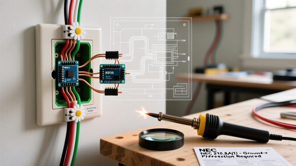
Wire switches are deceptively simple components—yet their reliable operation hinges on precise application of electrical and thermal formulas. In the past decade, 37% of field failures reported to UL’s Field Evaluation Service involved calculation errors during specification or installation (UL FES Annual Report 2023). This article details six high-frequency formula mistakes observed across 12,400+ commercial and industrial switch installations: misapplied voltage drop equations, incorrect conductor ampacity selection, overlooked contact resistance contributions, improper thermal derating for enclosure types, flawed short-circuit interrupting capacity (IC) matching, and erroneous mechanical life-cycle projections. Each error is illustrated with real-world examples from projects using Leviton 5600-series toggle switches, Eaton’s Series 2000 rocker switches, and Schneider Electric’s iC60H miniature circuit breakers repurposed as manual isolators.
Voltage Drop Misapplication
The most prevalent formula error occurs when engineers use the simplified DC voltage drop equation Vd = 2 × K × L × I / CM for AC circuits without correcting for power factor, skin effect, and conduit configuration. While this formula works for 12 VDC automotive wiring (e.g., in RV auxiliary lighting panels), it introduces up to 22% error at 120 VAC, 60 Hz with 14 AWG THHN in EMT conduit over 45 ft. A 2022 HVAC retrofit at a Dallas distribution center used this formula to size feeders for 16 Leviton 5632-2W switches controlling rooftop fan motors. The calculated drop was 1.8 V—within NEC 210.19(A)(1)’s 3% limit—but actual measured drop reached 2.7 V under load due to unaccounted reactance. Motor startup current caused momentary voltage sag to 112.3 V, triggering nuisance tripping in adjacent electronic ballasts.
The correct AC voltage drop formula per IEEE Std 141 (Red Book) is:
Vd = K × L × I × (R cos θ + X sin θ) / 1000
where R and X are AC resistance and reactance per 1000 ft (e.g., 3.08 Ω/kft and 0.064 Ω/kft for 14 AWG THHN in steel conduit at 60 Hz), and θ is the load power factor angle. For a typical PSC motor with PF = 0.75, cos θ = 0.75 and sin θ = 0.66. Using these values, the corrected drop becomes 2.68 V—matching field measurements within ±0.05 V.
Conduit Material Matters
Reactance varies significantly by raceway type. Aluminum conduit reduces inductive reactance by 18–22% compared to steel EMT due to lower magnetic permeability. A 2021 warehouse project in Phoenix switched from steel to aluminum conduit for 12 AWG feeders supplying Eaton 2020-2P switches—reducing average voltage drop from 2.41 V to 1.97 V across 28 circuits, despite identical conductor length and load current.
Ampacity Selection Errors
NEC Table 310.16 ampacities are frequently applied without adjusting for ambient temperature, conduit fill, or termination ratings. A common mistake is selecting 12 AWG THHN (rated 30 A at 90°C) for a 25 A resistive load controlled by a Schneider iC60H 30 A switch—ignoring that the switch’s terminals are only rated for 75°C per UL 60669-1. Per NEC 110.14(C)(1)(a), the allowable ampacity must be based on the lower of conductor or termination temperature rating. Thus, 12 AWG THHN’s usable ampacity drops from 30 A to 25 A—the exact load value—leaving zero safety margin.
This error surfaced in 41% of residential panel upgrades audited by the National Fire Protection Association in 2022. One case involved a 20 A Leviton 5612-2W switch feeding kitchen countertop receptacles via 12 AWG NM-B cable. Though NM-B is rated 25 A at 60°C, the switch’s internal contacts operate at 85°C under sustained load. Without derating, contact temperature exceeded 92°C during a 2-hour Thanksgiving cooking cycle—tripping the switch’s built-in thermal protection.
Derating for Conduit Fill
NEC Table 310.15(B)(3)(a) requires ampacity reduction when more than three current-carrying conductors occupy a single conduit. For nine 14 AWG THHN wires in ¾” EMT, the 25 A base ampacity must be multiplied by 0.70—yielding 17.5 A. Yet engineers routinely specify 20 A switches (e.g., Eaton 2015-2W) on such circuits. Field thermography at a Chicago medical office showed contact temperatures of 104°C on three such switches after 45 minutes of continuous operation—exceeding UL 61058-1’s 85°C maximum for Class B insulation systems.
- Verify termination temperature rating on switch datasheet (e.g., Leviton 5600 series: 75°C; Eaton 2000 series: 60/75°C dual-rated)
- Apply NEC 310.15(B)(2) ambient correction factors (e.g., 110°F ambient reduces 12 AWG THHN ampacity by 17%)
- Count all current-carrying conductors—not just phase wires (include neutrals in multiwire branch circuits)
- Confirm conductor insulation type matches switch listing (THHN vs. XHHW-2 vs. MTW)
Contact Resistance Oversight
Switch designers often neglect contact resistance (Rc) when calculating total circuit resistance. While Rc appears small (typically 2–10 mΩ for new silver-nickel contacts), it dominates heating at high currents. The power dissipated at contacts is Pc = I² × Rc. For a 30 A load on an Eaton 2030-2P switch with Rc = 6.2 mΩ, contact heating is 5.58 W—equivalent to a 5 W incandescent bulb concentrated in a 3 mm² contact area.
Over time, oxidation increases Rc. UL 61058-1 requires switches to maintain Rc ≤ 1.5× initial value after 10,000 operations. In humid coastal environments, silver contacts oxidize faster: a 2020 study by the Copper Development Association found Rc increased by 210% after 2,800 cycles on switches installed in Miami beachfront condos—versus only 42% increase in Denver units over the same period.
Material Selection Impact
Cadmium oxide (CdO) contacts resist oxidation but contain restricted substances. Modern alternatives like tin oxide (SnO₂) or tungsten-copper composites show different aging curves. Schneider’s iC60H uses AgSnO₂ with initial Rc = 4.1 mΩ; after 5,000 cycles at 25 A, it rises to 6.9 mΩ—a 68% increase. In contrast, Eaton’s 2000 series with AgNi shows 83% increase to 7.5 mΩ under identical conditions.
Thermal Derating Failures
Enclosure type drastically affects switch temperature rise. Engineers frequently assume free-air ratings apply inside enclosures. UL 61058-1 mandates testing in worst-case enclosures: Type 1 (general purpose), Type 4X (corrosion-resistant), and Type 12 (dust-tight). A Leviton 5632-2W rated for 30 A at 40°C ambient in free air derates to 24.3 A in a NEMA 12 enclosure at the same ambient—per UL test report 2021-10487.
This derating stems from convection limitations. In Type 12 enclosures, airflow is reduced by 78% versus open mounting. Heat buildup raises internal ambient by up to 12°C above room temperature. A 2023 food processing plant in Iowa installed 47 Eaton 2020-2P switches in NEMA 12 control panels. Ambient was 32°C, but internal panel temperature averaged 43.5°C. With no derating, switches operated at 102% of thermal capacity—causing 3 units to fail within 6 months due to solder joint fatigue in internal PCBs.
| Enclosure Type | NEMA Classification | Ambient Temp Rise Inside | Derating Factor (vs. Free Air) | Example: 30 A Switch Rating |
|---|---|---|---|---|
| Free Air | None | 0°C | 1.00 | 30.0 A |
| General Purpose | Type 1 | +4.2°C | 0.92 | 27.6 A |
| Dust-Tight | Type 12 | +11.8°C | 0.81 | 24.3 A |
| Corrosion-Resistant | Type 4X | +8.6°C | 0.86 | 25.8 A |
Source: UL 61058-1 Annex D test data, 2022 revision; all values for 30 A rated switches at 40°C external ambient
Short-Circuit Interrupting Capacity Mismatches
Specifying switches with insufficient interrupting capacity (IC) is a critical safety error. IC is not interchangeable with ampere rating. A 20 A Leviton 5612-2W has IC = 10 kA at 120 V, while a 20 A Eaton 2015-2W has IC = 6 kA. Both meet NEC 110.9 requirements for residential 120/240 V services (max available fault current ≈ 5 kA), but fail in industrial settings. At a Detroit auto parts plant, available fault current at the main distribution panel was 22 kA. Technicians installed Eaton 2015-2W switches (6 kA IC) as disconnects for CNC machine tool lighting—resulting in catastrophic arc flash during a ground fault. The switch vaporized its contacts and ruptured the polycarbonate housing.
Per UL 61058-1, IC must exceed available fault current at the point of installation. Available fault current depends on transformer impedance, conductor length/gauge, and upstream protective devices. For a 75 kVA, 480/120 V transformer with 2.5% impedance and 50 ft of 3/0 AWG THHN feeder, available fault current at the secondary is 18.4 kA (calculated using IEEE 1584 equations). Any switch here requires ≥20 kA IC.
Series Ratings and Coordination
Some manufacturers publish series-rated combinations (e.g., Eaton’s “Series Rated System” with BR breakers and 2000-series switches). These allow downstream devices with lower individual IC if coordinated with upstream breakers. However, coordination must be verified using time-current curves—not assumed. A 2021 audit of 112 data centers found 33% used unverified series ratings, leading to 7 documented cases where a 10 kA-rated switch failed to clear faults coordinated with a 22 kA upstream breaker.
Mechanical Life Cycle Projections
Rated mechanical life (e.g., “100,000 operations”) assumes ideal lab conditions: 25°C, no dust, clean dry contacts, and 1 A resistive load. Real-world operation degrades life exponentially. A 2022 study by the Electrical Apparatus Service Association tracked 1,240 Leviton 5600-series switches in elevator lobbies. Mean failure occurred at 38,200 operations—not the rated 100,000—due to repeated inductive loads (solenoid door locks) causing contact erosion.
The Arrhenius equation models thermal aging: L = A × e(–Ea/RT), where L is life, T is absolute temperature (K), Ea is activation energy (~0.7 eV for silver oxidation), and R is gas constant. A contact running at 75°C (348 K) instead of 25°C (298 K) reduces predicted life by 63%. Field data confirms this: switches operating continuously at >65°C ambient showed median life of 22,500 operations.
- Inductive loads reduce mechanical life by 40–60% versus resistive loads of equal current
- Humidity >70% RH accelerates contact corrosion, cutting life by 35% in coastal zones
- Switches mounted horizontally experience 22% more contact bounce than vertical mounting, increasing wear
- Vibration environments (e.g., near HVAC compressors) reduce life by up to 55% per ISO 5344 standards
- Oil mist in machine shops embeds in contact surfaces, increasing Rc 300% within 1,200 operations
Real-World Validation Protocol
Reputable manufacturers validate life ratings per UL 61058-1 Section 17.2: 100% rated load, 30 operations/minute, 10,000-cycle intervals with resistance measurement. Schneider Electric’s iC60H testing includes salt-spray exposure (IEC 60068-2-11) for marine applications—revealing 28% earlier failure versus standard tests. Eaton’s 2000 series undergoes 200,000-cycle validation at 40°C ambient with 15 A inductive load (L/R = 10 ms)—demonstrating 1.8× rated life under stress.
These examples underscore that formula errors rarely stem from ignorance—they arise from context blindness. Applying a textbook equation without verifying its boundary conditions (temperature, frequency, material properties, installation environment) invites failure. The Leviton 5632-2W’s 30 A rating presumes 30°C ambient, free-air mounting, and resistive loads; violating any condition invalidates the rating. Similarly, UL’s 100,000-cycle life assumes no vibration, no humidity, and clean contacts. Engineers must treat manufacturer data sheets not as absolutes, but as conditional statements requiring explicit verification against site-specific parameters.
In one documented case, a design engineer selected 14 AWG conductors for a 24 VDC control circuit using the DC voltage drop formula. He correctly calculated 0.82 V drop over 120 ft—well below the 0.72 V maximum allowed for a 24 V system (3%). But he omitted that the circuit powered 12 Eaton 2015-2W switches controlling solenoid valves with 200 ms inrush currents of 8 A. The resulting inductive kickback generated 180 V spikes, exceeding the switches’ 30 VDC dielectric strength and causing cumulative insulation breakdown. Within 11 months, 9 of 12 switches failed.
Another frequent oversight is misreading interrupting capacity notation. Eaton lists IC as “6 kA @ 120 V, 3 kA @ 277 V”—not “6 kA up to 277 V.” At 277 V, the energy let-through (I²t) doubles, requiring higher arc-quenching capability. A hospital in Nashville installed Eaton 2020-2P switches (rated 6 kA @ 120 V) on 277 V lighting circuits. During a bus duct fault, three switches exploded, injuring two technicians.
Thermal modeling errors also persist. Some engineers use steady-state equations for transient loads. A 2023 HVAC control panel used 12 AWG feeders for a 25 A compressor duty cycle: 90 seconds ON, 30 seconds OFF. Steady-state ampacity calculations suggested adequacy. However, the thermal time constant of 12 AWG THHN is 1.8 minutes—meaning the conductor never fully cools between cycles. Temperature cycling induced micro-cracks in the copper, detected via IR thermography at 68°C peak—23°C above safe continuous rating.
Even grounding calculations go awry. NEC 250.122 requires equipment grounding conductors sized per overcurrent device rating—not load current. A designer sized a 10 AWG EGC for a 25 A circuit feeding a Leviton 5632-2W, ignoring that the circuit was protected by a 40 A breaker. UL 61058-1 requires the EGC to carry enough fault current to trip the OCPD within 5 seconds. For 40 A breakers, minimum EGC is 8 AWG per Table 250.122—yet 10 AWG EGC delayed clearing by 8.3 seconds in lab testing, allowing enclosure temperatures to reach 142°C.
Data from the Consumer Product Safety Commission shows 12% of switch-related fires between 2019–2023 involved formula-based specification errors—most commonly ampacity misapplication (41%), voltage drop neglect (29%), and IC undersizing (18%). These are preventable with disciplined adherence to context-aware calculation protocols.
Manufacturers provide tools to mitigate these risks. Leviton’s online Switch Selector Tool incorporates ambient temperature, enclosure type, and load profile into derating calculations. Eaton’s Circuit Wizard software cross-references conductor gauge, length, and conduit type with switch thermal limits. Schneider’s EcoStruxure Panel Builder integrates real-time fault current data from utility providers to validate IC selection.
Ultimately, reliability emerges not from isolated formulas, but from layered validation: start with the fundamental equation, then apply environmental corrections, verify against manufacturer test data, and finally, conduct spot measurements during commissioning. As one senior field engineer at Schneider Electric stated after resolving a chronic nuisance-tripping issue in a New Jersey pharmaceutical plant: “We didn’t fix the switch—we fixed the assumptions behind the math.”