Feeding a subpanel from a main panel means running a dedicated multi-wire feeder circuit from a double-pole breaker in your primary service equipment to supply power to a secondary distribution board. When you execute this correctly, you change a home's electrical topology from a single, centralized hub into a distributed network, which reduces branch-circuit wire lengths, minimizes voltage drop, and provides localized disconnects for outbuildings or heavy-load zones. The most common point of confusion for DIYers is mixing up a subpanel's bus rating (the maximum current the metal and insulators can safely handle, often 125A) with the feeder breaker size (the actual overcurrent protection, often 60A). You can perfectly and legally feed a 125A-rated subpanel with a 60A breaker.
The Core Concept: Distributed Power and Local Disconnects
A main panel is the point of first disconnect where the utility's service drop meets your home's internal wiring. A subpanel is simply an extension of that system. To feed it, you need a 4-wire feeder: two ungrounded conductors (hots), one grounded conductor (neutral), and one equipment grounding conductor (EGC).
Why use four wires instead of the older three-wire method? The National Electrical Code (NEC) mandates a 4-wire feed to ensure that normal return current flows exclusively on the neutral wire, while the ground wire remains a dedicated, zero-current safety fault path. This separation prevents the metal chassis of your subpanel—and any appliances bonded to it—from becoming energized during normal operation.
The Golden Rule: Neutral and Ground Separation
If you take away only one rule from this guide, let it be this: the neutral and ground bars in a subpanel must never be bonded together.
In your main service panel, the neutral and ground are bonded (connected) at the main bonding jumper. This establishes the system's reference to earth ground. However, if you bond them again at a subpanel, you create a parallel neutral path. Because current takes all available paths, a portion of your 120V return current will flow back to the main panel over the bare copper ground wire. This energizes the grounding system, creating a severe shock hazard and causing nuisance tripping on upstream GFCI or AFCI breakers.
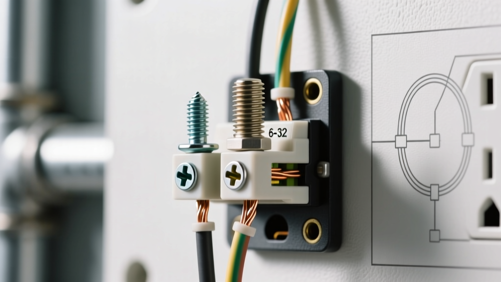
- Locate the bonding screw or strap: Every new subpanel ships with a green bonding screw or a copper bonding strap connecting the neutral bar to the metal enclosure.
- Remove it completely: Back it out and discard it or tape it to the inside of the panel cover for future reference.
- Add an isolated ground bar: If the panel doesn't have a dedicated, isolated ground bar, buy one that matches the panel brand (e.g., Square D HOM, Eaton BR) and mount it directly to the metal enclosure.
Sizing the Feeder: A Worked Numeric Example
Let's calculate the exact feeder requirements for a 60A subpanel located 100 feet away from the main panel. We will assume a standard 120/240V single-phase system, copper conductors, and termination ratings of 75°C (standard for modern breakers and lugs).
Step 1: Ampacity and Wire Sizing
A 60A double-pole breaker requires a conductor rated for at least 60A in the 75°C column of NEC Table 310.16.
- Copper: 6 AWG THHN is rated for 65A at 75°C. This is perfect for a 60A breaker.
- Aluminum: 4 AWG XHHW is rated for 65A at 75°C. Aluminum is cheaper but requires larger lugs and anti-oxidant paste.
Step 2: Voltage Drop Calculation
While the NEC recommends keeping feeder voltage drop under 3%, it is not strictly enforced unless specified by local amendments. Let's check the drop for our 6 AWG Copper run assuming a worst-case continuous load of 48A (80% of 60A).
The formula is: VD = (2 × K × I × D) / CM
- K (Copper resistivity) = 12.9
- I (Current) = 48A
- D (Distance) = 100 ft
- CM (Circular Mils for 6 AWG) = 26,240
VD = (2 × 12.9 × 48 × 100) / 26,240 = 4.72 Volts.
On a 240V circuit, 4.72V is a 1.96% drop. This is well within the 3% recommendation, meaning 6 AWG Copper is mathematically and legally sound for this run.
Where You Meet This in Practice
You will typically encounter the need to feed a subpanel in three specific residential scenarios:
- Detached Garages and Outbuildings: This is the most common application. Under NEC Article 250.32, a detached structure fed by a subpanel requires its own Grounding Electrode System (usually two 8-foot ground rods spaced 6 feet apart) bonded to the subpanel's isolated ground bar. The 4-wire feeder must still be run from the main, but the local ground rods handle localized earth potential.
- Basement Workshops or Heavy Load Zones: If you are adding a 240V welder, a large dust collector, and multiple 120V tool circuits, running individual home runs back to a main panel on the first floor is wasteful and causes severe voltage drop. A subpanel acts as a local distribution hub.
- Room Additions and ADUs: Accessory Dwelling Units (ADUs) often require their own subpanel to meet local code requirements for separate utility metering or localized disconnects, even if they share a physical wall with the main house.
Real-World Scenario: The Detached Garage Workshop
The Setup: A homeowner wants to power a detached garage 80 feet from the main house. The load includes a 40A Level 2 EV charger, a 15A table saw, a 15A dust collector, and LED lighting. They decide to install a 125A-rated main-lug subpanel in the garage, fed by a 60A breaker in the main house.
The Numbers: The calculated continuous load is roughly 45A. They pull four individual 6 AWG THHN wires (Black, Red, White, Green) through a buried 1-inch Schedule 80 PVC conduit. They drive two ground rods at the garage and bond them to the subpanel's ground bar.
The Outcome: The system powers up. The EV charger begins pulling 32A (the standard continuous draw for a 40A circuit). The lights work, and the table saw runs perfectly.
What Went Wrong: Three weeks later, the homeowner touches the metal track of the garage door while the EV charger is running and feels a distinct, tingling shock. Upon inspection, an electrician discovers the homeowner failed to remove the green bonding screw inside the new subpanel.
Because the neutral and ground were bonded at the subpanel, the 32A of return current from the EV charger split between the white neutral wire and the bare/green ground wire. The ground wire, which has resistance, experienced a voltage rise. Because the garage door track was bonded to the subpanel's ground bar, the track became energized with a few volts of potential relative to the earth. The fix was simple: de-energize the feeder, pull the subpanel cover, remove the bonding screw, and verify isolation with a multimeter. The shock hazard vanished immediately.