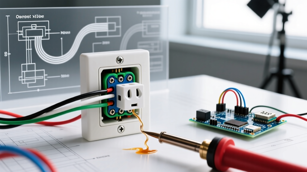
A switch symbol on a schematic represents a mechanical or solid-state device designed to open or close an electrical path. The exact symbol you draw or read depends entirely on the governing standard: US NEMA ladder logic, international IEC 60617, or physical residential wiring diagrams (NEC). Below is the master reference to decode these symbols and select the exact physical component you need for your bench or jobsite.
The Complete Switch Symbol Reference Table
The following table maps the most common switch types to their schematic representations across the two dominant global standards, alongside their physical residential equivalents and typical hardware store part numbers.
| Switch Type | NEMA (US) Symbol Description | IEC 60617 Symbol Description | Physical / Residential Equivalent | Typical Part Number |
|---|---|---|---|---|
| SPST (Single Pole, Single Throw) | Horizontal line broken by a diagonal lever | Horizontal line broken by a straight angled contact | Standard single-pole light switch | Leviton 1451-2W |
| SPDT (Single Pole, Double Throw) | Diagonal lever pivoting between two upper contacts | Angled contact pivoting between two horizontal lines | US '3-Way' residential switch | Leviton 5603-2W |
| DPST (Double Pole, Single Throw) | Two parallel SPST symbols linked by a dashed line | Two parallel IEC SPST symbols linked mechanically | 240V double-pole appliance switch | Eaton 1221-2W |
| DPDT (Double Pole, Double Throw) | Two parallel SPDT symbols linked by a dashed line | Two parallel IEC SPDT symbols linked mechanically | US '4-Way' residential switch (intermediate) | Leviton 5604-2W |
| Pushbutton (Normally Open) | Horizontal line with a vertical drop and upward diagonal | Horizontal line with a vertical drop and upward angled bridge | Momentary doorbell / start button | Schneider XB4BA31 |
| Pushbutton (Normally Closed) | Horizontal line with a vertical drop and downward diagonal | Horizontal line with a vertical drop and downward angled bridge | Momentary stop / emergency button | Schneider XB4BA42 |
| Limit Switch (Mechanical) | Standard NO/NC symbol with a roller or wedge actuator | Standard NO/NC symbol with a roller or wedge actuator | Industrial door interlock / CNC limit | Omron D4N-1A20 |
Regional Standards: NEMA vs. IEC vs. Old UK
Reading a schematic printed in Germany versus one printed in Ohio requires understanding the underlying standards body. Misinterpreting the regional standard is a primary cause of wiring errors in imported machinery.
NEMA (National Electrical Manufacturers Association)
Used predominantly in the US and Canada, NEMA symbols (often governed by NEMA ICS 1) are optimized for ladder logic. Switches are drawn with a distinct 'break' in a horizontal line, and mechanical linkages between poles are indicated by dashed lines. NEMA schematics prioritize readability for electricians tracing circuits from left to right.
IEC 60617 (International Electrotechnical Commission)
The IEC 60617 standard is the global baseline. IEC switch symbols use a more minimalist, geometric approach. A standard SPST is a simple angled line breaking a horizontal path. IEC diagrams often flow top-to-bottom and rely heavily on standardized reference designators (like -S1, -S2) rather than drawing out the physical layout of the contacts.
Old UK (Pre-2004 Harmonization)
Historically, the UK followed BS 3939 for graphical symbols, which was largely similar to early IEC standards but featured distinct physical wiring color codes (Red for Line, Black for Neutral, Green for Earth). While the UK harmonized its physical wire colors to the IEC standard (Brown, Blue, Green/Yellow) in 2004, you will still encounter old BS 3939 schematics in legacy industrial plants. The switch symbols themselves rarely cause confusion, but the wire colors attached to the physical switch terminals will bite you if you assume modern IEC colors.
Rows People Get Wrong (And How to Fix Them)
Even experienced makers and apprentice electricians trip over specific symbol-to-hardware translations. Here are the most common pitfalls.
Mistake 1: Confusing Schematic 'SPDT' with Hardware '3-Way'
In schematic theory, a Single Pole, Double Throw (SPDT) switch has one common terminal and two travelers. When you walk into a US hardware store to buy an SPDT switch for a residential lighting circuit, you must ask for a 3-way switch. If you ask for an 'SPDT', the clerk will hand you a toggle switch meant for a breadboard or low-voltage panel. Conversely, a US residential '4-way' switch is physically a DPDT switch wired internally as an intermediate crossover.
Mistake 2: Misreading NO vs. NC Pushbutton Slash Direction
On a NEMA diagram, a Normally Open (NO) pushbutton features a diagonal line pointing up and away from the contact point, indicating the contact must be pushed down to close. A Normally Closed (NC) pushbutton features a diagonal line pointing down and across the contact, indicating the circuit is closed at rest and must be pushed to break. Getting these backward in a motor control circuit will cause the motor to run when the stop button is pressed.
Mistake 3: Ignoring the 'Time Delay' or 'Thermal' Modifier
A standard switch symbol with a small curved line or a box attached to the actuator arm is not a standard toggle. It indicates a time-delay or thermal switch. If you see an SPST symbol with a small box and a 'TD' or thermal wave, do not install a standard mechanical toggle. You need a thermal cutoff or a time-delay relay module.
Decision Tree: Which Switch to Buy for Your Circuit
Use this decision path to translate your schematic requirement into a concrete hardware purchase. Do not guess; follow the logic to the exact part.
| Circuit Requirement | Schematic Symbol Needed | Physical Hardware to Buy | Exact Part Recommendation |
|---|---|---|---|
| Control a 120V light from one location | SPST | Single-Pole Toggle/Decora | Leviton 5601-2W (15A, 120V) |
| Control a 120V light from two locations | SPDT (x2) | US 3-Way Switch (Buy 2) | Leviton 5603-2W (15A, 120V) |
| Control a 120V light from three+ locations | SPDT (x2) + DPDT (x1) | Two 3-Way + One 4-Way Switch | Leviton 5604-2W (4-Way intermediate) |
| Reverse polarity on a 12V DC motor | DPDT (Center-Off) | DPDT Toggle, (ON)-OFF-(ON) | Browning BR125 (20A, 12VDC rated) |
| Disconnect both legs of a 240V dryer | DPST | Double-Pole Switch (30A+) | Eaton 1221-2W (30A, 120/277V) |
| Trigger an Arduino/ESP32 input safely | SPST (NO) | Momentary Tactile Pushbutton | Omron B3F-1000 (12x12mm, 50mA) |
Safe Interpretation When Markings Are Faded or Missing
On the jobsite or when salvaging industrial control panels, you will frequently encounter physical switches with faded terminal markings, missing schematic stickers, or painted-over labels. Never guess the terminal functions based on physical position. Use this continuity-testing protocol to map the switch safely.
Step 1: De-energize and Isolate
Turn off the breaker, apply a lockout/tagout (LOTO) if in an industrial setting, and verify the circuit is dead using a non-contact voltage tester and a multimeter set to AC/DC voltage. Never perform continuity tests on a live circuit. Disconnect at least one wire from the switch to prevent back-feeding through parallel circuit paths, which will give you false continuity readings.
Step 2: Map the Common Terminal (SPDT / 3-Way)
Set your digital multimeter to the continuity (beep) or lowest Ohms setting. 1. Place one probe on Terminal A and the other on Terminal B. Toggle the switch. Note the state (Open or Closed). 2. Move the second probe to Terminal C (keeping the first on A). Toggle the switch. 3. The terminal that shows continuity (< 1 ohm) to one of the other terminals in both toggle positions (just swapping between B and C) is your Common (COM) terminal. In US residential wiring, this is the dark-colored 'Line' or 'Load' screw. The other two are your Travelers (brass screws).
Step 3: Map a 4-Way (DPDT Intermediate)
A 4-way switch has four terminals. In Position 1, Terminal 1 connects to Terminal 3, and Terminal 2 connects to Terminal 4. In Position 2, the internal crossover swaps: Terminal 1 connects to Terminal 4, and Terminal 2 connects to Terminal 3. Map these pairs with your multimeter before wiring. If the switch fails to show clean < 1 ohm continuity and instead reads 5-10 ohms, the internal contacts are pitted from arcing and the switch must be replaced.
For further reading on standardizing your schematic documentation, refer to the All About Circuits switch types guide, which provides excellent visual breakdowns of internal contact mechanisms and their corresponding schematic representations.