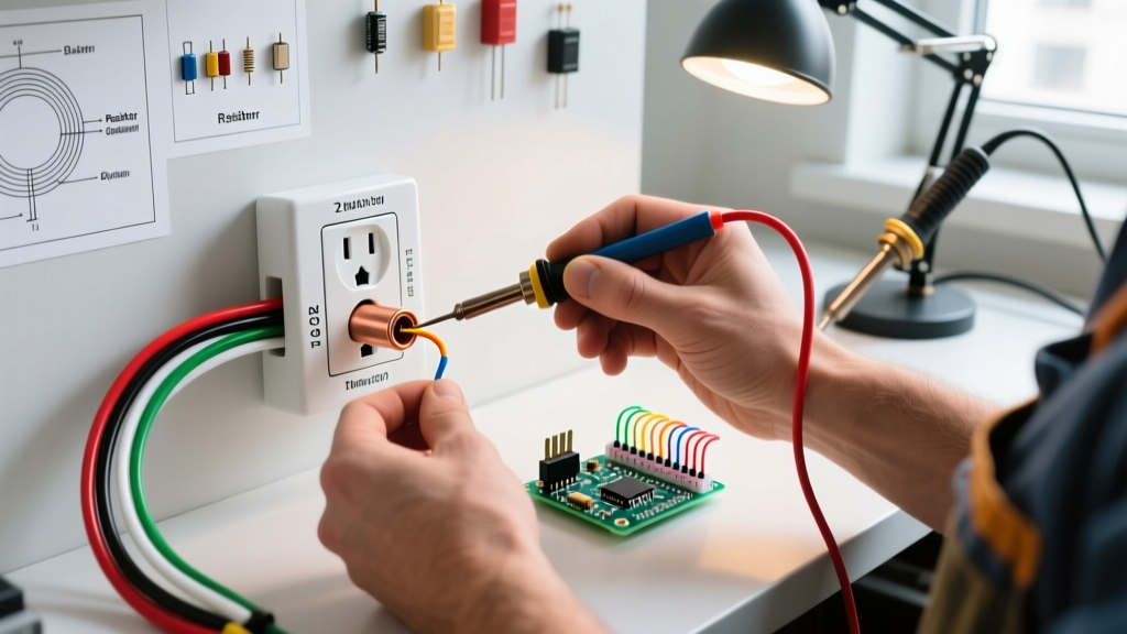
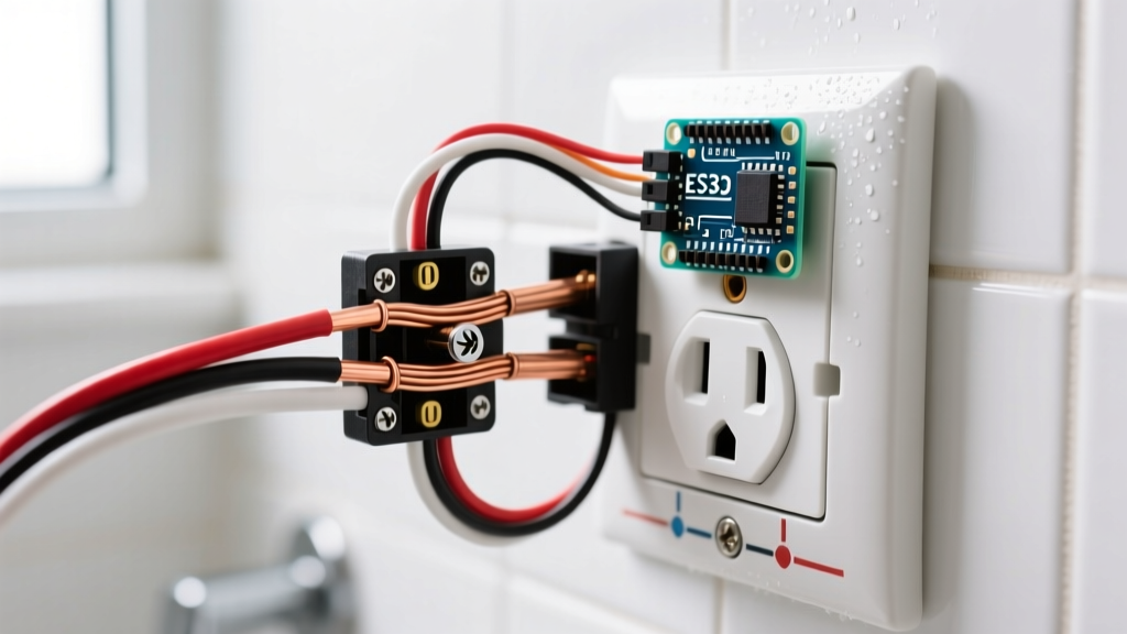
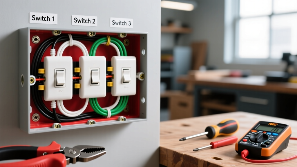
To properly define an electrical switch in the context of heavy loads, automation, and home subpanels, we must look beyond simple wall toggles. An electromechanical switch—specifically a heavy-duty relay or contactor—is a device where a low-power electromagnetic coil actuates a high-power mechanical contact set. This physical isolation allows a 24V DC microcontroller or PLC signal to safely switch a 240V AC compressor motor without exposing the low-voltage logic to mains hazards.
Unlike fuses or circuit breakers, which are overcurrent protective devices governed by specific time-current trip curves, a contactor is strictly a control device. It cannot safely interrupt a short circuit on its own and always requires a separate short-circuit protective device (SCPD), such as a motor protection circuit breaker, upstream. Understanding how to select, wire, and test these components is critical for any bench builder or panel wirer.
The Core Definition and Rating Matrix
When electrical engineers define an electrical switch for a motor control center or a home HVAC panel, they rely on standardized utilization categories outlined in IEC 60947 or UL 508. The most critical mistake DIYers make is looking only at the maximum amperage printed on the side of the device without checking the utilization category.
| Parameter | Typical Specification (e.g., 40A Contactor) | What It Governs |
|---|---|---|
| Coil Voltage | 24V DC, 120V AC, or 240V AC | The control circuit voltage required to pull in the armature. |
| Contact Rating (AC-1) | 50A at 600V | Non-inductive or slightly inductive loads (e.g., resistance heaters). |
| Contact Rating (AC-3) | 18A at 480V (approx. 10 HP) | Squirrel-cage motors: starting and switching off during running. |
| Breaking Capacity | 10x Ie (AC-3) | The maximum inrush current the contacts can safely interrupt without welding. |
Which rating column governs this load? The load type dictates the column. If you are switching a 30A resistive water heater, the AC-1 rating governs, and a 40A contactor is perfectly sized. If you are switching a 30A motor, the AC-3 rating governs. Because motors draw 6 to 8 times their full load amperage (FLA) during startup, a 40A contactor will weld its contacts shut on the first start cycle. You must size the contactor based on the AC-3 column for motor loads.
Coil vs. Contact Wiring and Protection
An electromechanical switch features two entirely isolated circuits: the coil (control) side and the contact (load) side. Mixing these up will instantly destroy your control board or create a lethal shock hazard.
- Coil Side (A1 and A2): These terminals connect to your control voltage. On a 24V DC system, A1 is typically positive and A2 is negative, though AC coils are non-polarized. Use 14 AWG to 18 AWG control wire, torqued to the manufacturer's spec (usually 1.2 Nm).
- Contact Side (L1/T1, L2/T2, L3/T3): These are the main power terminals. Line (source) connects to L1-L3, and Load connects to T1-T3. Use wire sized to the upstream breaker (e.g., 10 AWG THHN for a 30A circuit).
When you de-energize a DC coil, the collapsing magnetic field generates a massive reverse voltage spike (often exceeding 100V) that will fry the output transistor on your Arduino, ESP32, or PLC. You must wire a flyback diode (e.g., 1N4007) in reverse parallel across A1 and A2. Connect the diode's cathode (stripe) to A1 (positive) and the anode to A2 (negative). AC coils do not require this, as the alternating zero-crossing naturally collapses the field, though RC snubbers are sometimes used to reduce EMI.
Load Selection Decision Path
Selecting the right switch requires understanding the inrush characteristics of your specific load. Use the decision tree below to determine the required utilization category and sizing multiplier.
| Load Type | Examples | Inrush Multiplier | Governing Category | Sizing Rule |
|---|---|---|---|---|
| Resistive | Space heaters, incandescent lighting, oven elements | 1.0x to 1.2x (Cold filament spike) | AC-1 | Switch rating ≥ 100% of continuous load current. |
| Inductive (Non-Motor) | Control transformers, solenoid valves, ballasts | 3x to 5x | AC-14 / AC-15 | Switch rating ≥ 125% of continuous load current. |
| Motor (Squirrel Cage) | HVAC compressors, well pumps, conveyor belts | 6x to 8x (Locked Rotor Amperage) | AC-3 | Switch rating must match or exceed the motor's FLA in the AC-3 column. |
| Capacitive | Large capacitor banks, LED driver banks | 10x to 20x | AC-6b | Use contactors specifically rated for capacitor switching with pre-charge resistors. |
For home DIYers working under NFPA 70 (NEC) guidelines, remember that continuous loads (running for 3 hours or more) require the conductor and the switch to be derated to 125% of the nominal load. A 20A continuous heater requires a contactor rated for at least 25A, fed by 10 AWG wire on a 25A or 30A breaker.
Testing and Maintenance: Dead, Live, and Replacement
Electromechanical switches degrade over time. The mechanical armature wears out, and the electrical contacts pit from arc erosion. Here is how to diagnose them on the bench or in the panel.
How to Test It Dead (De-energized)
- Verify Zero Energy: Use a non-contact voltage tester and a multimeter to confirm the panel is dead. Lock out and tag out the breaker.
- Coil Resistance Test: Set your multimeter to Ohms (Ω). Probe A1 and A2. A healthy 24V DC coil typically reads between 15Ω and 50Ω. A 120V AC coil will read higher (100Ω to 400Ω). If it reads infinite (OL), the coil is burnt open. If it reads near 0Ω, the coil is shorted.
- Contact Continuity Test: Set the meter to continuity or low-ohms. Probe L1 and T1. With the armature at rest, it should read OL. Manually press the armature down with a plastic tool; it should read less than 0.5Ω. Repeat for all poles.
How to Test It Live (Energized)
Live testing should only be performed by qualified individuals wearing appropriate PPE.
- Coil Voltage: Measure across A1 and A2 while the system is calling for operation. If you read nominal voltage (e.g., 24.1V DC) but the contactor chatters or fails to pull in, the mechanical armature is jammed or the coil is failing under load.
- Voltage Drop Across Contacts: With the contactor pulled in and the motor running, measure the AC voltage between L1 and T1. A healthy contact will drop less than 0.1V. If you measure a voltage drop greater than 0.5V, the contacts are heavily pitted, generating excess heat, and failing.
When to Repair vs. Replace
The modern industry standard is to replace, not repair. A high-quality 40A DIN-rail contactor (like a Schneider TeSys D or Eaton XT) costs between $45 and $70. Attempting to refurbish it is a false economy.
- Repair: Only acceptable if the failure is external to the switch mechanism—such as a loose wire lug, a burnt control wire, or a field-replaceable coil on a massive NEMA-rated industrial contactor (where the unit costs $500+).
- Replace: Always replace if the contacts are pitted, welded, or blackened. Never use sandpaper or a file to clean silver-alloy contacts. Filing removes the protective cadmium-oxide or tin-oxide plating, which will cause the contacts to weld shut permanently on the next high-inrush start cycle.
Frequently Asked Questions
What is the exact definition of an electrical switch in a motor circuit?
In a motor circuit, an electrical switch is formally defined as a motor starter or contactor. It is a device designed to repeatedly establish and interrupt a motor's power circuit under normal running and starting conditions, but it does not provide short-circuit protection. It must be paired with an overload relay (to protect against sustained overcurrent) and a fuse or breaker (to protect against short circuits).
How do you define an electrical switch's breaking capacity versus its continuous rating?
Continuous rating (Ie) is the maximum RMS current the switch can carry indefinitely without the contacts overheating or exceeding a specific temperature rise (usually 60°C above ambient). Breaking capacity is the maximum current the switch can safely interrupt without the resulting electrical arc melting or welding the contacts together. For motor loads, the breaking capacity must handle the locked-rotor inrush current, which is why it is typically rated at 8 to 10 times the continuous AC-3 rating.
Can I define an electrical switch as a solid-state relay (SSR)?
While an SSR performs the same logical function—using a low-voltage signal to switch a high-voltage load—it is technically a semiconductor device, not an electromechanical switch. SSRs use TRIACs or MOSFETs to switch power. They offer silent, bounce-free operation and infinite mechanical life, but they suffer from continuous voltage drop (generating heat that requires a heatsink) and lack the physical air-gap isolation that makes electromechanical contactors inherently safer for maintenance lock-out/tag-out procedures.