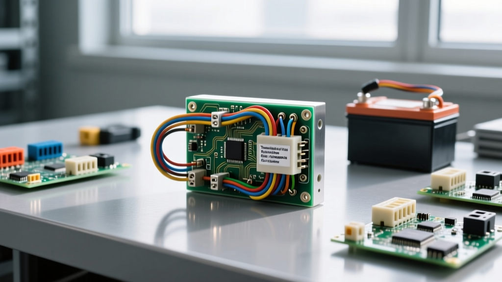

The Technician's Axiom: A diode in a wiring harness is a solid-state check valve. When it fails, it rarely does so quietly. It either creates a dead short that blows fuses instantly, or it fails open, allowing inductive spikes to weld relay contacts and destroy sensitive control modules. Proper diode wiring troubleshooting requires understanding both semiconductor physics and heavy-duty wire termination.
Diodes in the Wiring Harness: Beyond the PCB
When most people think of diodes, they picture tiny glass components soldered onto printed circuit boards. However, in general electrical wiring—particularly in automotive, marine, solar, and heavy machinery applications—diode wiring plays a critical role in harness protection and power routing. Inline diodes are heavily relied upon to prevent reverse current flow in dual-battery marine isolators, block feedback loops in complex HVAC control wiring, and suppress inductive kickback (flyback) in heavy-duty solenoid and relay circuits.
Troubleshooting these inline solid-state devices requires a different mindset than testing standard continuity. Unlike a simple wire or fuse, a diode introduces a forward voltage drop ($V_f$) and generates heat. When a wiring harness featuring diode protection begins to malfunction, the symptoms often mimic bad grounds, shorted coils, or undersized wire gauges. This guide provides a master-level diagnostic protocol for identifying, testing, and rewiring failed inline diodes.
Quick-Triage: Diode Failure Symptom Matrix
Before pulling out the multimeter, match your system's symptoms to this diagnostic matrix. Understanding the specific application of the diode wiring will dictate your testing approach.
| Application | Common Diode Type | Primary Failure Symptom | Root Cause of Wiring Failure |
|---|---|---|---|
| Relay Flyback (Control Harnesses) | 1N4001 / 1N4004 (Silicon) | Control switch melts; fuse blows instantly upon activation. | Diode wired in forward bias (creating a dead short), or diode failed open allowing inductive arcing. |
| Solar Blocking (DC Combiners) | Schottky (e.g., 30CPQ045) | Battery drains overnight; diode casing is melted or discolored. | Thermal runaway due to inadequate heat sinking or undersized wire gauge causing voltage drop. |
| Dual-Battery Isolator (Marine/Auto) | Heavy-Duty Stud Mount (100A+) | Secondary battery fails to charge; alternator whines or overheats. | Corrosion at the ring terminal crimp, or reverse bias avalanche breakdown from load dump spikes. |
The Multimeter Triage Protocol
To accurately troubleshoot diode wiring, you must isolate the component from the circuit. Testing a diode while it is still wired in parallel with a relay coil or a battery bank will yield false readings due to parallel resistance. Disconnect the power source and isolate the diode.
According to Fluke's official testing guidelines, you must use the dedicated Diode Test mode on your digital multimeter (DMM), not the standard continuity or ohms setting. The Diode Test mode applies a small, regulated current to measure the exact forward voltage drop.
Step-by-Step Inline Diode Testing
- Visual Inspection: Check the wiring harness for heat damage. If the heat shrink tubing around the diode is melted, or the wire insulation is brittle and cracking within two inches of the crimp, the diode has likely suffered thermal runaway.
- Forward Bias Test: Place the red multimeter probe on the anode (the side without the stripe) and the black probe on the cathode (the striped side). A healthy standard silicon diode will read between 0.5V and 0.8V. A Schottky diode will read lower, typically 0.2V to 0.4V.
- Reverse Bias Test: Swap the probes (red to cathode, black to anode). The meter should display OL (Open Loop) or a similar out-of-range indicator. If it reads 0.00V or beeps for continuity, the diode has suffered an internal short and must be cut out of the harness.
- The 'Leaky' Diode Check: If the reverse bias reading shows a voltage drop or a high resistance value instead of OL, the diode is 'leaking' current backward. In solar or battery isolation wiring, a leaky diode will slowly drain your battery bank over 24-48 hours.
Anatomy of Diode Wiring Failures
When troubleshooting, it is vital to understand why the diode wiring failed. Semiconductors are highly sensitive to their electrical and thermal environments. As detailed in fundamental guides like Electronics Tutorials, diodes operate within strict maximum ratings. Here are the three most common physical failure modes in general wiring applications.
1. Thermal Runaway and Heat Sink Deficiencies
Every diode introduces a forward voltage drop ($V_f$). This drop is converted directly into heat, calculated by the formula: Power (Watts) = $V_f$ × Current (Amps). If you wire a standard 0.7V silicon diode into a 50A alternator charging line, the diode will generate 35 Watts of heat. If this inline diode is merely crimped into a wire and wrapped in electrical tape without a massive heat sink, it will exceed its maximum junction temperature (usually 150°C) in seconds, melt the surrounding wire insulation, and fail short.
2. The Flyback Short-Circuit (Wiring Polarity Error)
Flyback diodes are wired across inductive loads (like relay coils or winch solenoids) to provide a safe path for the collapsing magnetic field when the switch opens. Crucially, a flyback diode must be wired in reverse bias relative to the supply voltage. If an apprentice wires the diode backward (forward bias), the moment the control switch is closed, the diode acts as a dead short across the power supply, instantly vaporizing the control fuse and potentially melting the wiring harness.
3. Reverse Avalanche Breakdown
Diodes have a Peak Inverse Voltage (PIV) rating. In automotive and marine wiring, 'load dump' scenarios (such as a battery cable disconnecting while the alternator is charging) can send transient voltage spikes exceeding 100V down a 12V harness. If the diode wired into the harness has a PIV rating of only 50V (like the common 1N4001), the spike will punch through the semiconductor junction, causing a catastrophic avalanche breakdown and a permanent short circuit.
Heavy-Duty Rewiring: Crimps, Solder, and Best Practices
Once you have identified a failed diode, the rewiring process must be executed to automotive or marine standards. Standard PCB soldering techniques do not apply to heavy-gauge wiring harnesses.
Why Soldering Inline Diodes Often Fails
Many DIYers attempt to solder heavy-duty diodes directly to 10 AWG or 8 AWG battery cables. This is a critical error. Solder has a relatively low melting point and is highly susceptible to fatigue from the vibration and thermal cycling inherent in engine bays and marine environments. Furthermore, large copper wires act as massive heat sinks, drawing heat away from the solder joint and leading to cold solder joints that introduce high resistance.
The Professional Standard: Use adhesive-lined marine heat shrink and a hydraulic or ratcheting wire crimper. Terminate the diode leads with the appropriate ring terminals or butt splices. For stud-mount diodes (common in battery isolation), apply a thin layer of dielectric grease to the stud threads and torque the nut to the manufacturer's specification to ensure a gas-tight, low-resistance connection.
Upgrading to Schottky and Ideal Diodes
If you are troubleshooting a recurring thermal failure in a high-current DC harness, consider upgrading the component. Replacing a standard silicon diode with a Schottky diode will cut the forward voltage drop in half (from ~0.7V to ~0.35V), effectively halving the heat generated. For ultra-high current applications like alternator isolation, modern wiring harnesses are moving away from solid-state diodes entirely, replacing them with MOSFET-based Ideal Diode Controllers, which reduce the voltage drop to mere millivolts, virtually eliminating heat generation.
Final Verification and Harness Routing
After completing the diode wiring repair, do not simply zip-tie the harness back into place. Diodes, even Schottky variants, will generate some heat under load. Ensure the repaired section of the wiring harness is routed away from exhaust manifolds, sharp metal edges, and moving linkages. If the diode requires a heat sink, ensure the heat sink fins are oriented to allow natural convective airflow.
Perform a final voltage drop test across the newly wired diode while the circuit is under maximum load. A voltage drop significantly higher than the diode's rated $V_f$ indicates a poor crimp connection or undersized wiring in the harness. By combining semiconductor diagnostics with master-level wire termination techniques, you ensure your electrical installations remain safe, efficient, and resilient against the harsh realities of real-world DC environments.


