
The Hidden Dangers of Light Fixture Electrical Wiring
Installing or replacing a ceiling luminaire is often treated as a beginner-level DIY task, but complacency during light fixture electrical wiring is a leading cause of residential electrical fires. According to the United States Fire Administration (USFA), electrical malfunctions in lighting and distribution systems cause thousands of home fires annually, resulting in millions in property damage. The danger rarely lies in the fixture itself; it lies in the junction box where thermal runaway, arcing, and improper grounding occur.
This guide bypasses basic 'how-to' fluff and focuses strictly on the safety best practices, National Electrical Code (NEC) mandates, and professional-grade execution techniques required in 2026 to ensure your lighting circuits remain safe, cool, and code-compliant for decades.
⚠️ CRITICAL SAFETY WARNING: Never rely solely on a wall switch to de-energize a circuit. Switches often break only the hot leg, and miswiring in older homes can leave the neutral or even the socket shell energized. Always verify zero energy at the junction box using a calibrated multimeter.NEC Mandates: Articles 410 and 314 Explained
Professional electricians adhere strictly to the National Fire Protection Association's NEC guidelines. For light fixture electrical wiring, two articles are your primary rulebooks:
1. Box Fill Calculations (NEC Article 314)
Overcrowding a junction box traps heat, degrading wire insulation over time and creating a severe fire hazard. You must calculate the cubic inch (cu in) capacity required before installing the fixture canopy or medallion.
- 14 AWG Wire: Requires 2.0 cu in per conductor.
- 12 AWG Wire: Requires 2.25 cu in per conductor.
- Clamps and Fittings: Count as 1 conductor volume based on the largest wire in the box.
- Fixture Studs/Hiccups: Count as 1 conductor volume.
Edge Case: If you are installing a heavy chandelier requiring a 4-inch octagon box, ensure the box is rated for the weight. Standard plastic nail-on boxes are typically rated for 50 lbs. For fixtures exceeding 50 lbs, NEC 410.30 requires independent structural support directly to the framing joist.
2. Luminaire Grounding (NEC Article 410.44)
Exposed metal parts of luminaires must be grounded. In modern 3-wire Romex (NM-B) installations, this means bonding the bare copper or green insulated equipment grounding conductor (EGC) to the fixture's green grounding screw. Never leave a metal fixture floating (ungrounded), as a short circuit to the metal housing will energize the entire fixture, posing a lethal shock hazard to anyone changing a bulb.
Pre-Installation Safety Matrix: Tools & PPE
Using the wrong tools for light fixture electrical wiring leads to damaged conductors and false voltage readings. Below is the professional safety matrix for residential lighting prep.
| Tool Category | Amateur / Unsafe Choice | Professional / Safe Choice (2026 Standard) |
|---|---|---|
| Voltage Verification | Generic $5 neon screwdriver tester | Fluke 117 True-RMS Multimeter (CAT III rated) |
| Wire Stripping | Utility knife or diagonal cutters | Klein Tools 11063W Automatic Wire Stripper |
| Connectors | Cheap, no-name twist-on wire nuts | Wago 221 Series Lever-Nuts (UL Listed) |
| Eye Protection | Standard reading glasses | ANSI Z87.1+ rated polycarbonate safety glasses |
Lockout/Tagout (LOTO) & The Live-Dead-Live Test
While OSHA's Lockout/Tagout standards are designed for industrial environments, the core principle is mandatory for safe residential light fixture electrical wiring. Simply taping the breaker is insufficient in a multi-occupant home.
- Identify and Isolate: Locate the exact breaker feeding the lighting circuit. Turn it OFF and apply a physical breaker lockout device (e.g., Schneider Electric HOM1LOCK) to prevent accidental re-engagement.
- Live-Dead-Live Verification:
- Live: Test your Fluke 117 multimeter on a known live source (like an outlet on a different circuit) to prove the meter works.
- Dead: Test the hot (black) to neutral (white), hot to ground (bare), and neutral to ground at the ceiling junction box. The reading must be 0.00V.
- Live: Test the known live source again to prove the meter did not blow a fuse or fail during the dead test.
Step-by-Step Execution: Preventing Failure Modes
The physical act of connecting wires is where 90% of long-term failures originate. Follow these precise execution steps to prevent thermal expansion issues and arcing.
Step 1: Precision Wire Stripping
Do not use a knife to score the insulation. Nicking the copper conductor creates a micro-fracture that becomes a high-resistance hot spot under load. Use an automatic stripper set to exactly 3/4 inch for standard wire nuts, or 11mm (7/16 inch) if using Wago 221 lever-nuts. The insulation should sit flush against the connector housing with no bare copper exposed outside the connection point.
Step 2: Termination (Wago vs. Twist-On)
In 2026, professional electricians heavily favor the Wago 221 Series Lever-Nuts over traditional twist-on connectors for light fixture electrical wiring.
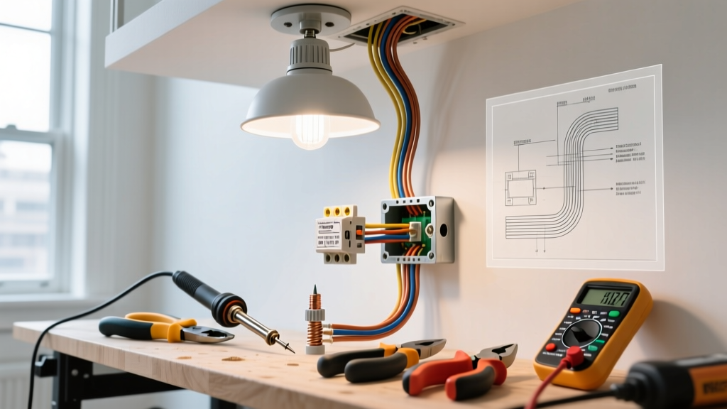
Why? Chandeliers and ceiling fans generate micro-vibrations. Over years of thermal cycling (heating and cooling), twist-on wire nuts can loosen, increasing resistance and causing arcing. Wago 221 connectors use a constant-pressure spring clamp that maintains a gas-tight connection regardless of vibration or thermal expansion. Furthermore, the transparent housing allows for visual verification that the wire is fully seated.
Step 3: Managing the 'Push-In' Backstab Trap
Many cheap, mass-produced light fixtures feature push-in (backstab) connectors on the socket terminals. Do not use them. These rely on a tiny metal tang biting into the wire. They are notorious for failing under the continuous draw of LED drivers or incandescent heat. Always loop the wire clockwise around the terminal screw and torque it firmly. If the fixture only has push-in pigtails, cut them off and use a Wago connector to adapt to your house wiring.
Edge Case: Grounding in Older 2-Wire Systems
What happens when you are installing a modern metal LED flush-mount fixture in a 1950s home with ungrounded 2-wire (black/white) cloth or early NM cable? You have no equipment grounding conductor (EGC).
"NEC 410.44 generally requires exposed metal parts to be grounded. However, Exception No. 2 allows for replacement of non-grounding luminaires if the fixture is made of non-conductive material (like glass or porcelain), or if the circuit is protected by a Ground Fault Circuit Interrupter (GFCI). You cannot simply leave a metal fixture ungrounded and call it safe."
The Safe Solution: If you must install a metal fixture on an ungrounded circuit, you must replace the standard breaker feeding that circuit with a GFCI breaker, or install a GFCI dead-front upstream. You must also label the fixture canopy with the provided 'No Equipment Ground' sticker. Better yet, upgrade the cable to modern NM-B with an EGC.
Summary of Critical Safety Tolerances
- Box Fill: Never exceed the stamped cubic inch rating of the junction box.
- Weight Limits: Fixtures over 50 lbs require independent joist mounting (NEC 410.30).
- Temperature Ratings: Ensure fixture wire leads (often rated for 90°C) are compatible with your branch circuit wire (typically 60°C or 90°C depending on NM-B age).
- Canopy Coverage: The fixture canopy must completely cover the junction box opening. No gaps, no exposed wire insulation, no drywall paper showing.
Proper light fixture electrical wiring is not just about making the bulb turn on; it is about engineering a connection that will withstand decades of thermal cycling, structural vibration, and environmental shifts. By adhering to NEC box fill rules, utilizing Live-Dead-Live testing, and upgrading to spring-clamp terminations like Wago 221s, you eliminate the primary vectors for residential electrical fires. When in doubt, or when faced with degraded aluminum wiring or missing grounds, invest the $125 to $175 average hourly rate for a licensed 2026 journeyman electrician to evaluate the circuit's integrity.