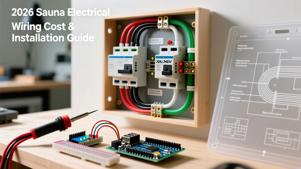
Grounding electrical systems establishes a low-impedance path back to the power source, ensuring overcurrent devices trip instantly during a fault while stabilizing system voltage to earth. If you are wiring a subpanel, replacing a receptacle, or troubleshooting a tripping GFCI, understanding the exact physics and code requirements of your ground path is the difference between a safe installation and a lethal hazard.
The Hazard: Chassis Energization and Arcing Faults
Before discussing wire sizes and color codes, we must establish what goes wrong when grounding is absent or compromised. The primary hazard is chassis energization. Imagine a 120V hot wire inside a metal-cased table saw vibrates loose and touches the chassis.
- Without a ground path: The metal casing sits at 120V. When you touch it, your body completes the circuit to earth. Assuming a wet-skin resistance of 1,000 ohms, Ohm’s law dictates 120mA will flow through your chest. This is well above the 50mA threshold for ventricular fibrillation.
- With a proper ground path: The fault current takes the low-impedance equipment grounding conductor (EGC) back to the panel. The massive surge of current (often hundreds of amps) instantly trips the 20A breaker, clearing the fault in milliseconds.
Grounding Electrical Systems: Sizing Data & Code Practice
When sizing conductors for grounding electrical systems, the National Electrical Code (NEC) splits the requirements into two distinct categories: the Equipment Grounding Conductor (EGC) that runs with your branch circuits, and the Grounding Electrode Conductor (GEC) that ties your main panel to the earth (via ground rods or a Ufer ground).
The table below outlines standard copper wire sizing based on NEC Tables 250.122 and 250.66. Note: These values assume standard 75°C copper terminations and residential 120/240V split-phase systems. This is NEC-style guidance; your local Authority Having Jurisdiction (AHJ) has final authority on all code compliance.
| Circuit / Service Rating | Copper EGC (Branch/Feeder) | Copper GEC (Main Service to Earth) | Application Notes |
|---|---|---|---|
| 15A / 20A Branch | 14 AWG / 12 AWG | N/A | Standard receptacle and lighting circuits |
| 30A Branch / Feeder | 10 AWG | N/A | Dryers, water heaters, small subpanels |
| 60A Subpanel Feeder | 10 AWG | 8 AWG (if acting as main) | Workshop or detached garage subpanels |
| 100A Main Service | 8 AWG | 8 AWG | Older residential main panels |
| 200A Main Service | 6 AWG | 4 AWG | Modern standard residential main panels |
Crucial Sizing Rule: If you upsize your ungrounded (hot) conductors to compensate for voltage drop over a long distance, NEC 250.122(B) requires you to proportionally increase the size of your EGC. If you run 8 AWG hots on a 20A circuit to prevent voltage drop over 150 feet, your ground wire must also be upsized from 12 AWG to 8 AWG.
Ground, Neutral, and Bond: The Critical Distinctions
The most common point of failure in DIY electrical work is confusing the neutral, the ground, and the bond. Understanding equipotential bonding—connecting all exposed metal to the same electrical potential so no voltage difference exists between them—requires knowing exactly what these three conductors do.
- Neutral (Grounded Conductor): This is the normal return path for current. It carries the exact same current as the hot wire during normal operation. It is insulated and colored white or gray.
- Equipment Ground (EGC): This is a safety shield. It carries zero current during normal operation. It only carries current during a fault. It is bare copper or green.
- The Bond (Main Bonding Jumper): This is the physical connection that ties the neutral and the ground together.
The Golden Rule: The neutral and ground must be bonded together at exactly one point in the system: the main service disconnect. If you bond them again at a subpanel, you create a parallel path. Normal neutral return current will split, with some portion flowing back on the bare ground wire. This energizes the grounding system, putting a few volts on the chassis of every metal appliance in your home and creating a severe shock hazard in wet locations.
Testing the Ground Path: Multimeter & Receptacle Testers
Verifying that your grounding electrical systems are functional requires more than just plugging in a $10 receptacle tester. While a 3-light tester (like the Gardner Bender GFI-3511) is a good first pass, it has a fatal blind spot: it cannot detect a "bootleg ground."
A bootleg ground occurs when a previous owner jumpered the neutral and ground screws on a 2-prong-to-3-prong receptacle adapter to trick a home inspector's 3-light tester. The tester will show "Correct," but the chassis of anything plugged into that outlet is directly tied to the current-carrying neutral wire.
How to Catch a Bootleg Ground with a Multimeter
- Measure Hot-to-Neutral: Set your multimeter to AC Volts. Place probes in the hot (short slot) and neutral (long slot). Note the reading (e.g., 120.5V).
- Measure Hot-to-Ground: Move the neutral probe to the ground hole. Note the reading (e.g., 120.2V).
- Analyze the Delta: If the two readings are identical (within 0.5V), you likely have a bootleg ground. A true, dedicated ground wire will show a slightly lower voltage than the neutral due to the voltage drop on the neutral wire under load.
- The GFCI Test: Plug in a dedicated GFCI receptacle tester and press the test button. A true ground will trip the GFCI or breaker. A bootleg ground will often fail to trip the upstream protection, revealing the fake ground.
For whole-house verification or troubleshooting ground loops in sensitive AV equipment, professionals use a ground impedance tester (such as the Fluke 1630-2) to measure the exact resistance of the earth ground path, ensuring it meets the NEC requirement of 25 ohms or less for a single ground rod.
When to Call a Licensed Electrician
While swapping receptacles and wiring branch circuits is well within the scope of a competent DIYer, certain aspects of grounding electrical systems involve extreme risk and legal code requirements that mandate a licensed professional.
- Service Entrance Work: Any work on the service drop, meter base, or main service panel involves exposed, unfused utility power. A mistake here bypasses your main breaker and can result in an arc flash or utility-side fault.
- Driving Ground Rods: Driving an 8-foot copper-clad steel ground rod requires calling 811 to locate underground utilities. Hitting a gas line or fiber optic cable is a catastrophic, potentially fatal error.
- Upgrading Main Bonding: If you are upgrading from a 100A to a 200A service, the main bonding jumper and GEC must be recalculated and installed to exact torque specifications.
Always consult the NFPA 70 National Electrical Code for the most current article revisions, and refer to OSHA electrical safety guidelines when working on live panels. For deep-dive theory on grounding versus bonding, Mike Holt's NEC illustrations remain the industry benchmark for visualizing fault current paths. When in doubt, pull the permit, hire the pro, and let the AHJ inspector verify your work.