
Why Choose a Ground Plate Electrode for Your Home?
When establishing a reliable grounding system for a residential electrical service, most electricians default to driving copper-clad ground rods into the earth. However, geological realities do not always cooperate. If your property features shallow bedrock, highly compacted clay, or soil with exceptionally high resistivity, driving an 8-foot or 10-foot rod may be physically impossible or electrically insufficient. In these scenarios, a ground plate electrode becomes the most practical and code-compliant solution.
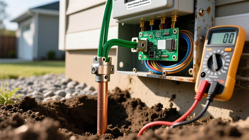
A ground plate electrode relies on horizontal surface area rather than vertical depth to establish a low-impedance path to the earth. By burying a conductive plate in a carefully prepared trench, homeowners and electricians can achieve a stable reference to ground potential, ensuring that fault currents have a safe path to trip breakers and that surge protection devices function correctly.
Safety Warning: Before breaking ground on any trenching project, always call 811 (or your local utility locating service) at least 48 hours in advance. Striking an underground gas, water, or primary electrical line can be fatal and carries massive financial liability.
NEC Article 250: Material and Sizing Requirements
The National Electrical Code (NEC), specifically NFPA 70 Article 250.52(A)(7), dictates the exact specifications for plate electrodes. You cannot simply bury a scrap piece of sheet metal and call it a day. To ensure longevity against galvanic corrosion and to provide adequate conductive mass, the NEC mandates the following:
- Copper Plates: Must have a minimum surface area of 2 square feet (e.g., 1 ft x 2 ft or 1.41 ft x 1.41 ft) and a minimum thickness of 0.060 inches (1.5 mm).
- Galvanized Iron or Steel Plates: Must have a minimum surface area of 3 square feet (e.g., 1.5 ft x 2 ft) and a minimum thickness of 1/4 inch (6.4 mm).
- Burial Depth: The plate must be buried at a minimum depth of 2.5 feet (800 mm) below the surface of the earth to ensure it remains in contact with moist soil year-round, below the typical frost line in many temperate climates.
Furthermore, the Electrical Contractor Magazine (ECMAG) frequently highlights that the connection between the plate and the Grounding Electrode Conductor (GEC) must be listed for direct burial if it is not going to be kept in an accessible handhole or junction box.
Ground Plate vs. Ground Rod: Which is Right for Your Soil?
Understanding when to pivot from a traditional rod to a plate is a hallmark of advanced residential wiring. Below is a decision matrix to help you evaluate your specific site conditions.
| Feature | Copper Ground Rod (5/8" x 8') | Copper Ground Plate (2' x 2') |
|---|---|---|
| Installation Effort | High (requires hammering or rotary hammer in rocky soil) | Moderate (requires trenching and backfilling) |
| Ideal Soil Type | Deep, loamy, or moist soils free of large boulders | Shallow soils, bedrock layers, or high-resistivity sand |
| Surface Area Contact | Approx. 1.3 sq. ft. (lateral surface area) | 4.0 sq. ft. (both sides of the plate) |
| Frost Heave Risk | Low (driven deep below frost line) | Moderate (must be buried below local frost line) |
| Material Cost | $40 - $80 | $150 - $350+ |
Step-by-Step Installation Guide
Step 1: Site Selection and Trenching
Select a location near your main electrical panel that is naturally shaded or retains moisture, such as near a downspout or on the north side of the home. Avoid placing the plate near concrete foundations, as concrete can leach alkaline chemicals that accelerate the corrosion of copper over decades. Dig a trench that is at least 30 inches deep and wide enough to comfortably maneuver (typically 12 to 18 inches wide). If you are installing the plate horizontally, the trench floor must be leveled.
Step 2: Soil Preparation and Ground Enhancement Material (GEM)
Soil resistivity is the single biggest factor in grounding efficacy. If your soil is rocky or sandy, direct contact with the copper plate will be poor. To solve this, line the bottom of the trench with a layer of conductive backfill. Bentonite clay is a traditional, cost-effective option that swells when wet, holding moisture against the plate. For superior performance, use a carbon-based Ground Enhancement Material (GEM), such as nVent GEM or generic conductive cement. Mix the GEM with water to a slurry consistency and pour a 2-inch bed at the bottom of the trench.
Step 3: Plate Placement and Backfilling
Lower the copper ground plate electrode into the trench. While the NEC does not strictly mandate horizontal or vertical orientation, laying the plate flat on the GEM bed maximizes the surface area exposed to the moisture-holding backfill. Once the plate is positioned, cover it with another 2 inches of GEM or bentonite clay. After the conductive layer encapsulates the plate, backfill the remainder of the trench with the native soil you excavated, tamping it down every 6 inches to eliminate air pockets that could dry out and increase resistance.
Step 4: Attaching the Grounding Electrode Conductor (GEC)
The wire connecting your panel's neutral/ground bus bar to the plate is the GEC. According to NEC Table 250.66, the minimum size for a GEC connected to a ground plate is 8 AWG copper. However, for modern 200-amp residential services, electricians typically run 4 AWG or 6 AWG bare copper to provide mechanical protection and lower overall impedance.
Because the connection point will be buried and inaccessible, you cannot use a standard brass acorn clamp. You must use an exothermic welding kit (like a Cadweld connection) or a mechanical clamp specifically listed and marked for "Direct Burial." Exothermic welding creates a molecular bond between the copper wire and the plate, eliminating the risk of galvanic corrosion and loosening over time.
Testing and the 25-Ohm Rule
NEC Section 250.56 states that if a single rod, pipe, or plate electrode does not achieve an earth resistance of 25 ohms or less, it must be supplemented by an additional electrode. In residential construction, measuring exact earth resistance requires a specialized fall-of-potential ground tester, which can cost thousands of dollars.
Because of this, many local inspectors allow the "exception" route: installing a second ground plate (or a ground rod) spaced at least 6 feet apart from the first, effectively bypassing the requirement to measure the 25-ohm threshold. If you are doing this as a DIY home project, installing two plates connected via a continuous, unspliced GEC is the safest way to guarantee code compliance without renting expensive testing equipment.
Common DIY Mistakes to Avoid
- Using Aluminum Plate: Aluminum is strictly prohibited for direct burial grounding electrodes due to rapid galvanic corrosion in soil.
- Splicing the GEC: The Grounding Electrode Conductor must be continuous from the panel to the plate. If you must use two lengths of wire, they must be connected using an irreversible compression connector or exothermic weld, never a standard wire nut or split bolt.
- Shallow Burial: Burying the plate only 12 inches deep to save on digging time violates the 2.5-foot minimum rule and leaves the electrode susceptible to seasonal drying, which will cause your ground resistance to spike in the summer months.
- Painting the Plate: Never coat the plate in anti-corrosive paint or bitumen. The plate must be bare metal to allow electrical current to transfer into the surrounding soil matrix.
Installing a ground plate electrode is a labor-intensive but highly rewarding home wiring project. By adhering strictly to NEC material requirements, utilizing conductive backfills, and ensuring your connections are rated for direct burial, you will provide your home's electrical system with a robust, low-impedance path to earth that will last for generations.