
Navigating the Battery Wiring Fleetwood RV Electrical Schematic
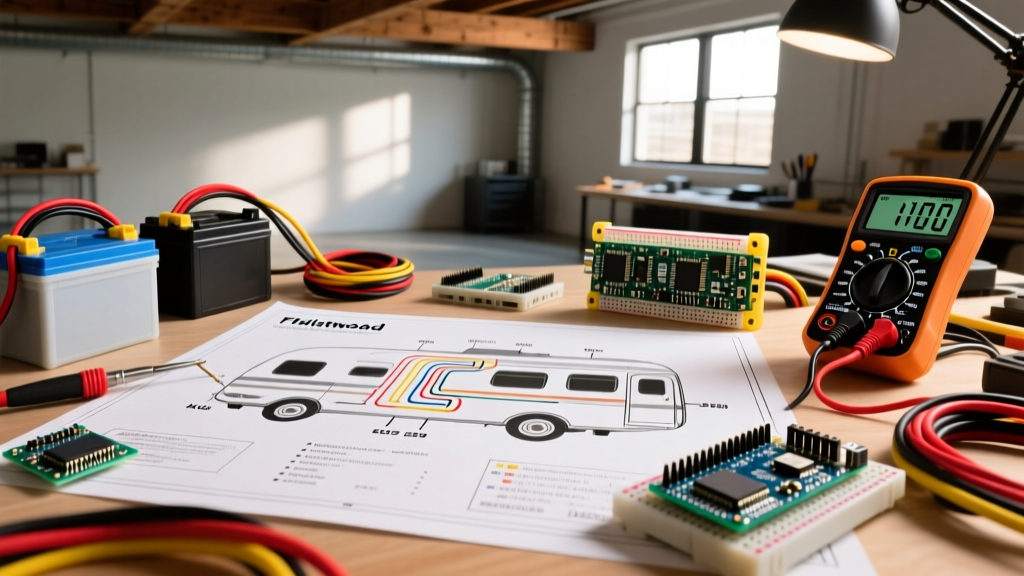
Fleetwood motorhomes, including the iconic Bounder, Southwind, and Discovery lines, feature some of the most complex 12V DC and 120V AC integration platforms on the road. When owners decide to upgrade their aging lead-acid battery banks to modern LiFePO4 lithium systems, install high-wattage solar arrays, or troubleshoot a parasitic draw, the mandatory first step is consulting the battery wiring Fleetwood RV electrical schematic. However, possessing the schematic and successfully executing a safe, code-compliant wiring overhaul are two vastly different challenges.
In this comprehensive analysis, we break down the exact technical requirements hidden within Fleetwood's wiring diagrams and evaluate the real-world costs, risks, and outcomes of tackling the project as a DIY enthusiast versus hiring a certified RV electrical technician in 2026.
Anatomy of the Fleetwood Battery Schematic
Before deciding who should hold the wire strippers, you must understand what the schematic actually dictates. Fleetwood's 12V architecture relies heavily on a BIRD (Bi-Directional Isolator Relay Delay) system to manage charging between the chassis (starter) and house (coach) batteries.
Core Components You Will Encounter
- The BIRD Relay & Trombetta Solenoid: The schematic details a 12V control circuit that triggers a heavy-duty Trombetta solenoid (often part #70-111224). This solenoid physically bridges the chassis and house battery banks when the alternator or shore power charger exceeds 13.1V.
- Inverter/Charger Integration: Most 2015-2025 Fleetwood models utilize Magnum Energy (now Sensata) inverter/chargers, such as the Magnum ME-2812 or MS2812. The schematic maps the 2/0 AWG DC leads directly from the house battery bus to the Magnum's DC terminals, alongside the ME-ARC50 remote control network wiring.
- The "Salesman" Switch: A latching relay circuit designed to disconnect 12V house loads during storage. The schematic reveals how this switch interacts with the main DC breaker panel and the battery disconnect solenoid.
The DIY Route: Upgrading to Lithium Using the Schematic
Armed with the factory schematic, many technically inclined RVers opt to replace their heavy, sulfated AGM or flooded lead-acid batteries with lightweight lithium iron phosphate (LiFePO4) alternatives. Let us analyze the reality of this DIY approach.
Real-World Material Costs (2026 Pricing)
A standard DIY lithium upgrade for a Fleetwood Bounder requires significant capital. Replacing four 6V golf-cart batteries with a robust lithium bank involves:
- Batteries: 2x Victron Smart Lithium 200Ah 12.8V batteries (approx. $2,600 total) or 4x Battle Born 100Ah GC2 (approx. $3,400 total).
- DC-DC Charger: Because the Fleetwood BIRD system and standard automotive alternator are not designed for the low-impedance draw of lithium, a DIYer must install a DC-DC charger (e.g., Victron Orion-Tr Smart 12/12-30) to protect the alternator. Cost: $280.
- Wiring & Busbars: 25 feet of 2/0 AWG pure copper welding cable, heavy-duty adhesive heat shrink, and a 600A Blue Sea Systems busbar. Cost: $220.
- Monitoring: Victron SmartShunt 500A for accurate state-of-charge tracking via Bluetooth. Cost: $165.
Total DIY Material Cost: $3,265 to $4,065.
The DIY Execution and Hidden Risks
The primary advantage of the DIY route is labor savings. However, misinterpreting the Fleetwood schematic carries severe risks. A common DIY failure mode occurs when owners wire the new lithium BMS directly to the existing BIRD solenoid. If the house bank drops to 11.5V and the alternator pushes 14.2V, the BIRD engages. A depleted 400Ah lithium bank can instantly pull 150+ amps from a standard 140A chassis alternator, leading to catastrophic alternator overheating and failure within minutes.
Furthermore, DIYers often neglect torque specifications. Magnum Energy explicitly requires DC terminal lugs to be torqued to 10 to 12 ft-lbs. Hand-tightening these connections leads to micro-arcing, melted terminal blocks, and potential DC electrical fires.
The Professional Installation Analysis
Hiring an RVIA-certified technician or a specialized mobile RV electrician shifts the burden of liability, code compliance, and schematic interpretation to an expert. In 2026, the demand for certified RV techs has driven labor rates up, but the value proposition remains strong for complex Fleetwood systems.
Professional Pricing and Scope of Work
Expect to pay between $145 and $195 per hour for a certified RV electrical specialist. A complete Fleetwood lithium upgrade, including schematic tracing, BIRD system bypass/modification, DC-DC charger installation, and load testing, typically takes 12 to 18 hours of shop time.
- Labor Cost: $1,740 to $3,510.
- Markup on Parts: Shops typically add a 15% to 20% markup on batteries and wire, adding roughly $500 to the material cost.
- Total Professional Cost: $5,500 to $8,000+.
The Expert Advantage
Professionals do not just follow the schematic; they audit it against current safety standards. According to the Recreation Vehicle Industry Association (RVIA) and guidelines mirroring NFPA 1192 (Standard on Recreational Vehicles), all DC wiring must be protected within 18 inches of the power source with a Class T fuse or ANL fuse. A pro will replace outdated factory breakers with properly sized Class T fuses (e.g., a 400A Class T for a 400Ah lithium bank) and use thermal imaging cameras to verify that no connection exceeds ambient temperature by more than 10°C under full inverter load.
Head-to-Head Matrix: DIY vs. Certified RV Technician
| Parameter | DIY Installation | Professional RV Technician |
|---|---|---|
| Total Cost (2026) | $3,265 - $4,065 | $5,500 - $8,000+ |
| Time Investment | 15 - 30 hours (weekends) | 1 - 2 days (shop time) |
| Schematic Interpretation | Self-taught; high risk of misreading BIRD logic | Expert; understands factory anomalies and revisions |
| Warranty & Liability | Voided if improper wiring causes inverter failure | 1-year warranty on labor; full manufacturer warranty |
| Tooling Required | Hydraulic crimper, torque wrench, multimeter ($250+) | Thermal camera, milliohm meter, calibrated torque tools |
Critical Schematic Traps and Edge Cases
Whether you turn the wrench or pay someone who does, be aware of these specific Fleetwood schematic edge cases that routinely cause electrical failures:
Expert Warning: The Chassis Ground Fallacy
Many older Fleetwood schematics show the house battery negative terminal grounding directly to the steel chassis frame. When upgrading to high-draw lithium systems and 3000W inverters, relying on the chassis frame as a negative return path introduces massive voltage drop and stray current corrosion. Always run a dedicated 2/0 AWG or 4/0 AWG negative cable directly from the inverter's negative busbar to the house battery negative terminal, completely bypassing the chassis frame for high-current DC returns.
The Inverter Control Board Vulnerability
Fleetwood routes the Magnum inverter's network cable (RJ11/RJ45 style) parallel to 120V AC Romex in some manufacturing runs to save time. The schematic might not explicitly warn against this. If a DIYer replaces wiring and zip-ties the low-voltage Magnum ME-ARC network cable tightly against 120V AC lines, electromagnetic interference (EMI) will corrupt the data signal, causing the inverter to throw phantom "Stacking Error" or "Comm Fault" codes. Professionals know to maintain a minimum 4-inch separation between AC and DC control wiring.
The Final Verdict: Which Path Should You Take?
The decision to use the battery wiring Fleetwood RV electrical schematic for a DIY project or to hire a professional ultimately depends on your baseline electrical competency and risk tolerance.
When to DIY
Choose the DIY route if you have prior experience with DC electrical systems, own a calibrated torque wrench and hydraulic lug crimper, and understand the vital difference between series and parallel battery configurations. If you are simply swapping like-for-like AGM batteries and cleaning corroded busbars, the factory schematic is straightforward enough for a careful weekend warrior. Furthermore, utilizing resources from Magnum Dimensions to cross-reference your specific inverter model's installation manual will bridge the gaps left by Fleetwood's generalized coach schematics.
When to Hire a Professional
You must hire a certified technician if you are migrating from lead-acid to lithium, adding high-wattage solar charge controllers, or if your schematic includes a multiplexed CAN-bus system (common in newer Fleetwood Discovery models with SilverLeaf electronics). The cost of a single mistake—such as frying a $2,200 Magnum inverter control board or starting a DC fire due to an improperly crimped 2/0 AWG lug—far exceeds the $2,500 premium you pay for professional labor. In the realm of high-amperage DC RV wiring, precision and code compliance are not optional; they are the difference between a reliable off-grid adventure and a catastrophic failure.