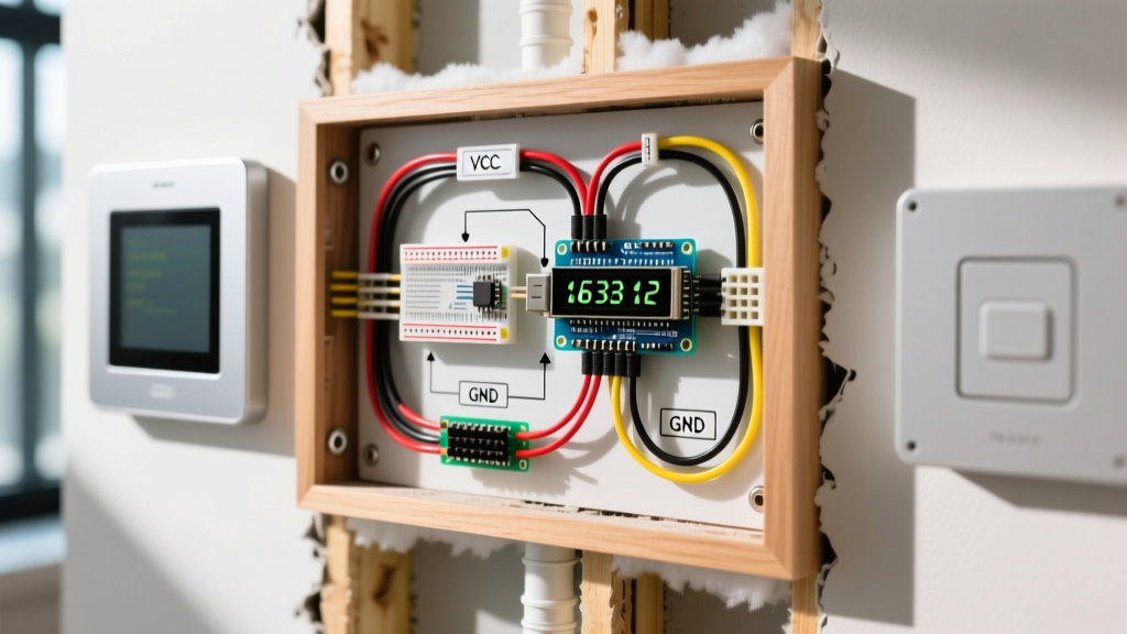

The Renovation Blueprint: Integrating Custom Smart Panels
When planning a whole-home renovation or a dedicated smart-home retrofit, the cost of commercial in-wall control panels quickly compounds. Outfitting a multi-zone HVAC system or a custom lighting array with proprietary smart displays can easily exceed $250 per interface. For the DIY renovator and electrical enthusiast, building custom control nodes using a microcontroller and a character or TFT screen is a highly cost-effective alternative. However, executing Arduino LCD display wiring inside finished walls requires a fundamental shift from breadboard prototyping to architectural low-voltage planning.
Unlike standard 120V/240V rough-ins, low-voltage data and power lines are highly susceptible to voltage drop, electromagnetic interference (EMI), and bus capacitance. This guide details how to properly plan, route, and terminate your Arduino LCD display wiring during the demolition and rough-in phases of your renovation, ensuring your custom smart panels work flawlessly once the drywall is painted.
The I2C Capacitance Problem: Why Standard Wiring Fails In-Wall
The most common mistake renovators make when planning Arduino LCD display wiring is assuming they can mount the microcontroller in a centralized basement server rack and run 15-foot I2C cables through the studs to a wall-mounted LCD. This will almost always fail.
The I2C protocol, which drives 90% of hobbyist LCD backpacks (like the ubiquitous PCF8574T), has a strict maximum bus capacitance limit of 400pF. Standard 24 AWG unshielded wire carries a capacitance of roughly 15pF to 20pF per foot. A 15-foot run introduces ~300pF of capacitance before you even factor in the LCD module and the microcontroller's internal pins. The result? Corrupted data, ghost characters, and complete bus lockups.
Renovation Rule of Thumb: Never run raw I2C lines through wall cavities for distances exceeding 1 meter (3.3 feet). For in-wall smart panels, the microcontroller must be mounted locally behind the display inside the wall box, and only robust power and differential data signals should be routed back to your central hub.
Topology Shift: Centralized vs. Local Node Wiring
To achieve reliable Arduino LCD display wiring in a remodel, you must adopt a "Local Node" topology. Below is a comparison of how wiring strategies must adapt for permanent architectural installations.
| Topology Strategy | Microcontroller Location | Wiring Run Through Studs | Max Distance | Renovation Viability |
|---|---|---|---|---|
| Direct I2C (Standard) | Central Hub / Basement | 4-wire I2C (SDA, SCL, VCC, GND) | ~3 feet | Poor (High failure rate) |
| I2C Bus Extender | Central Hub / Basement | CAT5e/6 with P82B96 extender chips | ~100 feet | Moderate (Requires custom PCBs) |
| Local Node (Recommended) | In-Wall (Behind LCD) | 12V Power + CAT6 (RS485/UART) | 300+ feet | Excellent (Industry standard) |
Step-by-Step: Local Node Arduino LCD Display Wiring
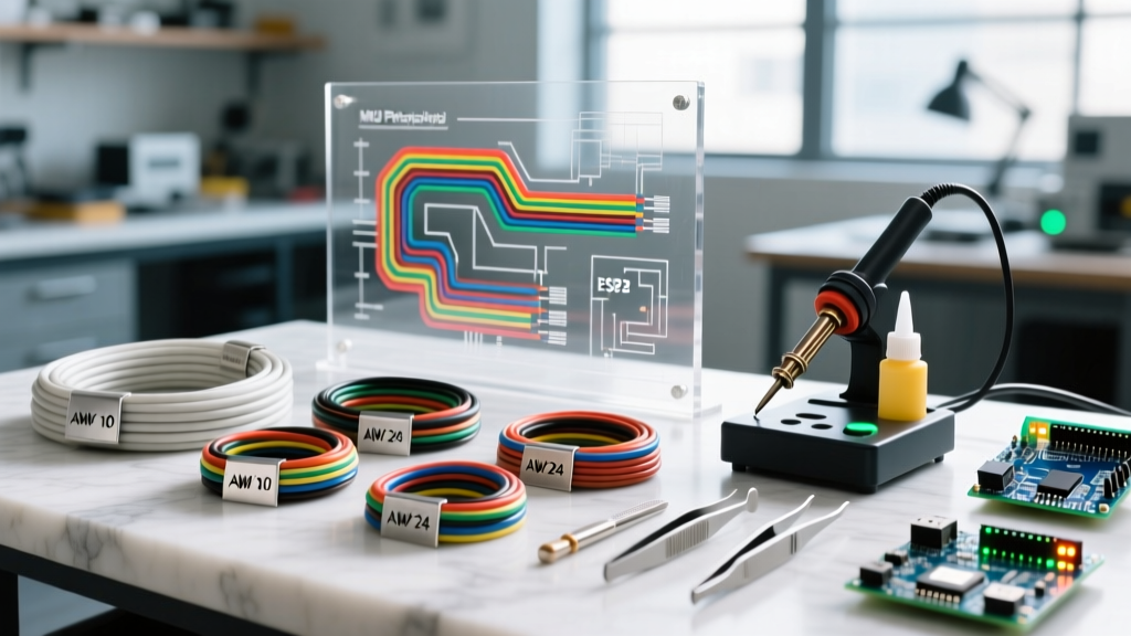
For this renovation scenario, we are installing a 20x4 character LCD (model 2004A with an I2C backpack) paired with an ESP32 DevKit V1 for Wi-Fi/Bluetooth connectivity, powered via a 12V-to-5V buck converter. The total BOM cost per node is approximately $24, compared to $250+ for commercial equivalents.
1. Rough-In: Selecting the Right Wall Box and Conduit
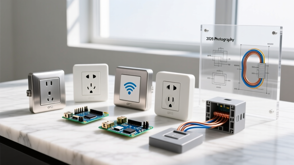
Do not use standard metal 1-gang electrical boxes for your smart displays. Metal boxes act as a Faraday cage, severely degrading the ESP32's Wi-Fi signal, and they lack the depth required to house the Arduino, the buck converter, and the wiring harness.
- Box Selection: Use an extra-deep, non-metallic low-voltage mounting bracket (e.g., Carlon B114R or Arlington Industries LV1). These cost about $2.50 each and provide ample cubic-inch volume for wire management.
- Conduit Routing: Run a dedicated 3/4-inch flexible non-metallic conduit (smurf tube) from your central low-voltage distribution panel to the wall box. This allows you to pull new wires in the future without tearing open drywall.
2. Power Delivery and Voltage Drop Mitigation
Running 5V USB power over 20 feet of 22 AWG wire will result in a severe voltage drop, causing the LCD backlight to flicker and the Arduino to brownout and reset. According to standard electrical wiring practices for low-voltage remodels, you should distribute higher voltage and step it down locally.
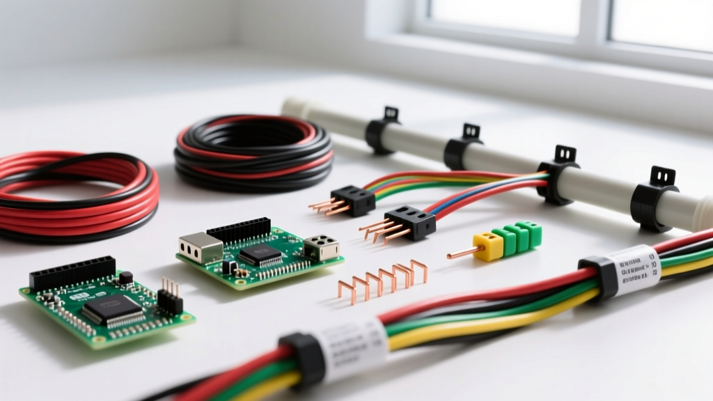
- Run 18 AWG CL2-rated stranded copper wire (like Belden 8760) through the conduit to deliver 12V DC from a centralized, UL-listed Class 2 power supply.
- At the wall box, wire the 12V lines into an LM2596 step-down buck converter module.
- Adjust the LM2596 potentiometer with a multimeter to output exactly 5.1V to compensate for the 0.1V drop across the I2C backpack's diode.
- Connect the 5V and GND outputs directly to the VCC and GND pins of the LCD's PCF8574 backpack.
3. Terminating the Arduino LCD Display Wiring (I2C)
With the Arduino mounted securely inside the deep wall box (using double-sided VHB tape or a custom 3D-printed sled), the actual Arduino LCD display wiring is kept to a minimum, localized entirely within the gang box.
- SDA (Serial Data): Connect Arduino GPIO 21 (on ESP32) or A4 (on Nano) to the SDA pin on the LCD backpack.
- SCL (Serial Clock): Connect Arduino GPIO 22 (on ESP32) or A5 (on Nano) to the SCL pin.
- Pull-Up Resistors: Because the wire run is less than 6 inches, the standard 4.7kΩ pull-up resistors on the I2C backpack are sufficient. No external pull-ups are required for this localized topology.
For further reading on I2C addressing and ensuring your specific LCD backpack doesn't conflict with other sensors in the wall box, consult the Adafruit I2C Address Guide.
NEC Compliance for Low-Voltage Remodels
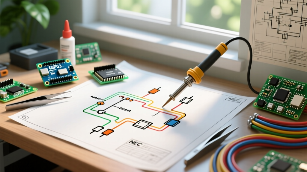
Even though you are working with 12V and 5V DC, the National Electrical Code (NEC) strictly governs how low-voltage wiring interacts with mains voltage during a renovation. Under NFPA 70 (NEC) Article 725, Class 2 and Class 3 circuits must be physically separated from Class 1 (120V+) circuits.
- Separation Distance: Maintain a minimum of 2 inches of separation between your 12V DC Arduino power lines and any 120V AC Romex runs inside the wall cavity, unless a physical barrier (like a steel stud or conduit) is installed between them.
- Box Sharing: Never route your Arduino's 12V power into the same junction box as 120V AC mains unless the box has a certified, permanently installed metal divider.
- Plenum Ratings: If your conduit runs through a dropped ceiling that acts as a return air plenum, you must use CMP (Plenum-rated) cables to prevent toxic smoke circulation in the event of a fire.
Data Communication: Bridging the Wall to the Hub
While the Arduino LCD display wiring handles the local interface, the ESP32 still needs to communicate with your home automation server (like Home Assistant). Relying solely on Wi-Fi through walls can be unreliable. For a robust renovation, pull a CAT6 cable alongside your 12V power lines.
Wire the CAT6 to the ESP32's UART pins (TX/RX) and use an RS485 transceiver module (like the MAX485) at both ends. RS485 uses differential signaling, making it entirely immune to the EMI generated by nearby AC wiring, dimmers, and HVAC blowers. This ensures your custom LCD panel receives real-time temperature and lighting state updates without latency or packet loss.
Troubleshooting Common In-Wall Display Failures
Even with meticulous planning, post-drywall testing can reveal issues. Here is how to diagnose the most common edge cases:
The "Ghost Character" Flicker
Symptom: The LCD displays random, flickering blocks or Japanese characters. Diagnosis: This is almost always caused by EMI induction from a nearby AC dimmer switch or a loose ground connection on the LM2596 buck converter. Fix: Ensure the GND of the buck converter is shared with the ESP32's GND. If the issue persists, wrap the I2C jumper wires in copper foil tape and ground the tape to the Arduino's GND pin to create a localized Faraday shield.
Backlight Illuminated, But No Text
Symptom: The screen glows blue/white, but no characters appear, even after adjusting the contrast potentiometer.
Diagnosis: The I2C bus is hanging, usually due to an incorrect address or missing pull-up resistors.
Fix: Run an I2C scanner sketch (available via the Arduino Wire Library Documentation). Many cheap PCF8574 backpacks use the address 0x27, but some use 0x3F. Update your code's initialization string accordingly.
ESP32 Brownouts During Backlight Activation
Symptom: The Arduino resets whenever the LCD backlight is turned on via software. Diagnosis: The LCD backlight draws up to 120mA. If powered directly from the ESP32's onboard 5V pin, it exceeds the linear regulator's thermal limits. Fix: Wire the LCD VCC directly to the 5V output of the LM2596 buck converter, bypassing the Arduino's voltage regulator entirely. Use a MOSFET (like the IRLZ44N) controlled by an Arduino GPIO to switch the backlight ground if software dimming is required.
Final Renovation Sign-Off
Integrating custom electronics into a home's permanent infrastructure bridges the gap between software engineering and general electrical wiring. By respecting the physical limitations of the I2C protocol, utilizing localized step-down power delivery, and adhering to NEC low-voltage separation codes, your Arduino LCD display wiring will survive the rough-in phase and provide a reliable, custom smart-home interface for years to come. Always test your complete node assembly on a workbench before the insulation and drywall crews arrive on site.