
Electricity is only as safe as the materials that confine it. While conductors get all the glory for delivering power, insulators are the unsung heroes of electrical safety, preventing catastrophic shorts, fires, and fatal shocks.
When building or repairing electrical systems, understanding the barrier between current and the environment is critical. But beyond simply 'plastic around a wire,' what is an insulator of electricity at a fundamental level? How do engineers choose between PVC, XLPE, and PTFE for specific applications? This guide explores the quantum physics, material science, and real-world failure modes of electrical insulation.
The Atomic Reality: What Is an Insulator of Electricity?
To understand insulation, we must look at the atomic structure of materials. According to Georgia State University's HyperPhysics, the electrical behavior of a solid is dictated by its 'band structure'—specifically, the relationship between the valence band (where electrons are bound to atoms) and the conduction band (where electrons are free to move and carry current).
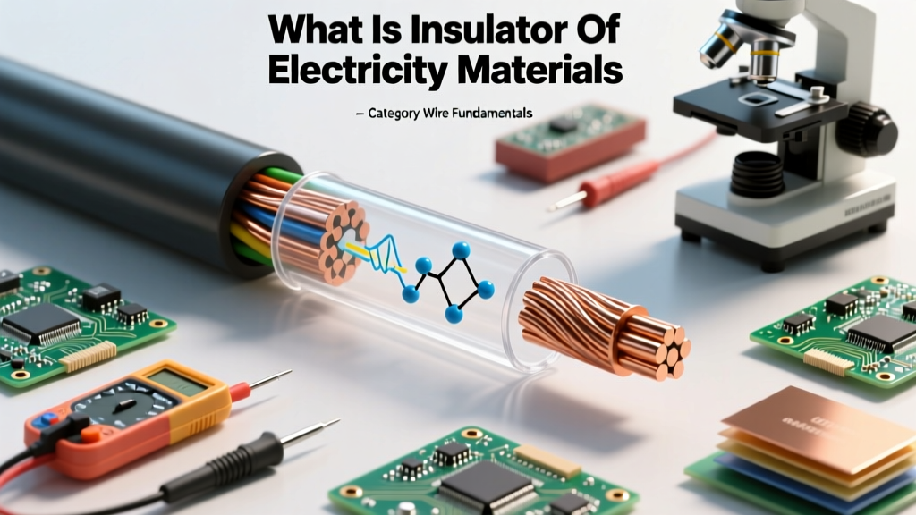
In a conductor like copper, these bands overlap, allowing electrons to flow freely with minimal energy. In an insulator, there is a massive 'forbidden zone' or band gap between the valence and conduction bands. For a material to be an effective electrical insulator, this band gap typically exceeds 5 electron volts (eV). Because the energy required to excite an electron across this gap is far greater than the voltage provided by standard electrical systems, the electrons remain tightly bound to their atoms, effectively blocking current flow.
Dielectric Strength vs. Insulation Resistance
A common mistake among DIYers and junior technicians is conflating dielectric strength with insulation resistance. While both describe insulating performance, they measure entirely different physical phenomena.
- Insulation Resistance: Measured in Megohms (MΩ), this is the material's ability to prevent leakage current. It is a measure of how well the insulator resists the slow trickle of electrons through its bulk or across its surface. High insulation resistance is crucial for signal integrity and preventing ground faults.
- Dielectric Strength: Measured in kilovolts per millimeter (kV/mm) or Volts per mil (V/mil), this is the maximum electric field the material can withstand before it experiences dielectric breakdown—a catastrophic puncture where the insulator suddenly becomes a conductor, resulting in an arc or short circuit.
Data from The Engineering Toolbox highlights how vastly different materials perform under high-voltage stress. Below is a comparison of common wire insulation polymers.
| Insulation Material | Dielectric Strength (kV/mm) | Max Continuous Temp (°C) | Primary Wire Application |
|---|---|---|---|
| PVC (Polyvinyl Chloride) | 15 - 20 | 75 - 90 | Standard THHN/THWN building wire |
| XLPE (Cross-Linked PE) | 20 - 25 | 90 - 105 | High-voltage underground, industrial feeders |
| PTFE (Teflon) | 60 - 100 | 250 | Aerospace, high-frequency coaxial cables |
| Silicone Rubber | 20 - 30 | 150 - 200 | High-temp appliance wiring, flexible robotics |
| EPR (Ethylene Propylene) | 25 - 35 | 90 - 105 | Medium-voltage utility distribution |
Real-World Wire Insulation Materials (Beyond Basic PVC)
While PVC is the undisputed king of residential wiring due to its low cost and flame retardancy, demanding environments require advanced polymer chemistry.
PVC and Polyamide (The THHN Standard)
Standard building wire, such as THHN (Thermoplastic High Heat-resistant Nylon-coated), actually uses a dual-layer approach. The primary dielectric barrier is PVC, which provides excellent electrical isolation and contains chlorine for inherent flame resistance. However, PVC is mechanically soft and susceptible to chemical degradation. To solve this, manufacturers extrude a thin outer jacket of Polyamide (Nylon). The nylon provides immense tensile strength, reduces friction for pulling wire through conduit, and resists oil and gasoline, all while allowing the wire to maintain a slim profile.
XLPE (Cross-Linked Polyethylene)
Standard polyethylene melts at relatively low temperatures, making it useless for high-current wires that generate heat. XLPE solves this through a chemical or irradiation process that creates cross-links between the polymer chains, transforming the thermoplastic into a thermoset material. This means XLPE will not melt or deform even if the copper conductor reaches extreme temperatures during a short-circuit event. It is the standard for NFPA 70 (National Electrical Code) compliant high-voltage and underground feeder cables.
PTFE (Teflon) & FEP
Fluoropolymers like PTFE offer the highest dielectric strength and the lowest dielectric constant of almost any solid material. This makes them indispensable in high-frequency data cables (like Category 6a or aerospace coaxial cables) where signal attenuation and capacitance must be minimized. PTFE can withstand continuous temperatures up to 250°C, making it ideal for military and aerospace applications where weight and thermal extremes are critical factors.
Failure Modes: When Insulators Become Conductors
Insulators do not last forever. Environmental stress, electrical abuse, and mechanical damage can compromise the band gap, leading to catastrophic failure. Understanding these failure modes is vital for troubleshooting and preventative maintenance.
Thermal Degradation and Carbon Tracking
When an insulator is subjected to temperatures beyond its thermal rating, the polymer chains begin to break down. In organic polymers like PVC or Rubber, this thermal decomposition releases volatile gases and leaves behind elemental carbon. Because carbon is highly conductive, this creates a phenomenon known as carbon tracking. An initial micro-arc burns a microscopic path through the insulation, depositing carbon. This carbon path lowers the insulation resistance, drawing more leakage current, which creates more heat and more carbon. Eventually, a fully conductive carbon bridge forms, resulting in a dead short, a massive arc flash, and often a fire.
Corona Discharge and Ozone Cracking
In high-voltage applications (typically above 2,000V), the electric field gradient near the conductor can become so intense that it ionizes the surrounding air, creating a 'corona discharge.' This ionization process generates ozone (O3) and nitric acid. Ozone is highly reactive and aggressively attacks the double-bond carbon chains found in natural rubber and EPR insulation. This causes micro-cracking on the surface of the wire, which eventually penetrates deep into the dielectric barrier, leading to moisture ingress and ultimate dielectric breakdown.
Practical Selection Framework for DIY and Industrial Wiring
Choosing the right insulation is not just about matching the voltage rating; it requires analyzing the operational environment.
- Ambient Temperature: If routing wires through an engine bay, near a kiln, or inside high-density LED lighting fixtures, abandon standard 90°C THHN. Upgrade to Silicone Rubber or PTFE to prevent thermal embrittlement.
- Mechanical Stress: For robotics, CNC machines, or drag chains where the wire will be flexed millions of times, avoid rigid PVC which will crack. Use specially formulated PUR (Polyurethane) or continuous-flex Silicone compounds.
- Chemical Exposure: In manufacturing plants where wires are exposed to cutting fluids, oils, or solvents, standard PVC will swell and dissolve. Specify XLPO (Cross-Linked Polyolefin) or Fluoropolymer jackets.
- UV and Moisture: For outdoor or direct-burial applications, ensure the insulation is rated for UV resistance (often indicated by a black jacket with carbon black additives) and moisture resistance, such as USE-2 or XHHW-2 rated cables.
Ultimately, an insulator is the physical manifestation of electrical control. By respecting the atomic limitations and environmental vulnerabilities of these materials, engineers and electricians ensure that power remains exactly where it belongs: inside the conductor.