
Why Guessing Wire Gauge is a Fire Hazard
Every year, thousands of residential electrical fires are traced back to a single, preventable failure: undersized conductors. When DIYers rely on rule-of-thumb guessing rather than a verified wire size chart, they invite catastrophic Joule heating. The physics are unforgiving. Power dissipated as heat in a conductor is calculated by the formula P = I²R (Current squared multiplied by Resistance). If you push 20 Amps through a 14 AWG copper wire designed for 15 Amps, you aren't just exceeding the limit by 33%; you are increasing the thermal output by nearly 78%. Over time, this excess heat bakes the PVC or XLPE insulation, causing it to become brittle, crack, and eventually expose bare conductors to combustible framing materials.
As a safety-first knowledge hub, ElectricalFlux emphasizes that a wire size chart isn't just a suggestion—it is the distilled wisdom of the National Electrical Code (NEC) and decades of forensic fire investigation. Below, we break down the exact parameters you need to size your circuits safely, legally, and efficiently.
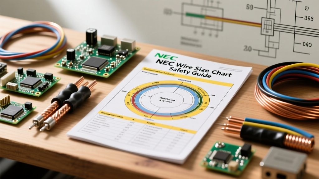
The Master Wire Size Chart (AWG to Ampacity)
The following chart is based on CerroWire's official ampacity tables and aligns with NEC Article 310.16 for single-insulated copper conductors in a raceway or cable.
| AWG Size | Diameter (Inches) | Circular Mils (CM) | Cu. Ampacity (60°C) | Cu. Ampacity (75°C) | Cu. Ampacity (90°C) |
|---|---|---|---|---|---|
| 14 | 0.0641 | 4,110 | 15A | 20A | 25A |
| 12 | 0.0808 | 6,530 | 20A | 25A | 30A |
| 10 | 0.1019 | 10,380 | 30A | 35A | 40A |
| 8 | 0.1285 | 16,510 | 40A | 50A | 55A |
| 6 | 0.1620 | 26,240 | 55A | 65A | 75A |
| 4 | 0.2043 | 41,740 | 70A | 85A | 95A |
| 3 | 0.2294 | 52,620 | 85A | 100A | 115A |
| 2 | 0.2576 | 66,360 | 95A | 115A | 130A |
| 1/0 | 0.3249 | 105,600 | 125A | 150A | 170A |
| 2/0 | 0.3648 | 133,100 | 145A | 175A | 195A |
| 4/0 | 0.4600 | 211,600 | 195A | 230A | 260A |
Decoding the Temperature Columns
The most common mistake DIYers make when reading a wire size chart is blindly using the 90°C column because THHN/THWN-2 wire is rated for it. Stop. NEC Section 110.14(C) dictates that the ampacity of a circuit is limited by the lowest temperature rating of any connected component. Standard residential breakers and receptacles are typically rated for 75°C, while older devices or specific lighting fixtures may only be rated for 60°C. Therefore, a 12 AWG wire on a standard 20A residential breaker must be sized using the 60°C or 75°C column (both safely allow 20A), not the 90°C column.
Voltage Drop: The Hidden Danger Ignored by Basic Charts
A standard wire size chart assumes a short run. It does not account for resistance over distance. If you are wiring a 240V, 30A garage heater located 120 feet from your main panel, using 10 AWG copper (the standard chart recommendation for 30A) will result in severe voltage drop. This forces the heater's motor or elements to draw excess current to compensate, leading to overheating and premature failure.
The NEC recommends a maximum voltage drop of 3% for branch circuits. To calculate this, use the standard single-phase voltage drop formula:
VD = (2 × K × I × D) / CM
- K = Specific resistance (12.9 for Copper, 21.2 for Aluminum)
- I = Current in Amps
- D = One-way distance in feet
- CM = Circular Mils (from the chart above)
For our 30A garage heater at 120 feet using 10 AWG (10,380 CM):
VD = (2 × 12.9 × 30 × 120) / 10,380 = 8.94 Volts.
On a 240V circuit, 8.94V is a 3.7% drop, which exceeds the 3% safety threshold. To fix this, you must step up to 8 AWG (16,510 CM), which drops the VD to 5.62V (2.3%), ensuring safe, efficient operation. Always use a dedicated voltage drop calculator for runs exceeding 50 feet.
Aluminum vs. Copper: Sizing Discrepancies and Oxidation
Modern aluminum alloys (like AA-8000 series) are safe and code-compliant for feeder wires and heavy appliance circuits, provided you respect the wire size chart discrepancies. Aluminum has higher resistance than copper, meaning you must typically increase the wire size by two AWG steps to carry the same current. For example, where 6 AWG copper handles 55A (60°C column), you need 4 AWG aluminum to achieve the same ampacity.
Critical Safety Warning: Aluminum oxidizes rapidly when exposed to air, creating a highly resistive surface layer that causes terminal connections to overheat and arc. If you are terminating aluminum wire, you must use CO/ALR rated receptacles or dual-rated (CU/AL) lugs, and you must coat the stripped conductor with an antioxidant compound like Noalox. Never use standard brass-only terminals for aluminum branch circuits.
Grounding Conductor Sizing (NEC Table 250.122)
Standard ampacity charts do not apply to Equipment Grounding Conductors (EGCs). The ground wire doesn't carry current under normal operation; it must safely carry massive fault currents long enough to trip the breaker. If you upsize your current-carrying conductors for voltage drop, NEC 250.122(B) requires you to proportionally upsize your ground wire as well.
| Breaker / OCPD Rating | Minimum Copper EGC | Minimum Aluminum EGC |
|---|---|---|
| 15A - 20A | 14 AWG | 12 AWG |
| 30A | 10 AWG | 8 AWG |
| 40A - 60A | 10 AWG | 8 AWG |
| 100A | 8 AWG | 6 AWG |
| 200A | 6 AWG | 4 AWG |
Real-World Troubleshooting: When the Chart Fails You
A wire size chart is based on ideal conditions: an ambient temperature of 30°C (86°F) and no more than three current-carrying conductors in a single raceway. Real-world DIY environments rarely match this. If you are pulling wire through an attic in Texas where ambient temperatures reach 125°F, or bundling multiple 12 AWG cables through a single bored hole in a top plate, the chart's ampacity limits are legally and physically void.
According to NFPA 70 (NEC) Article 310.15(C)(1), if you have 4 to 6 current-carrying conductors bundled together for more than 24 inches, you must apply an 80% derating factor. If you have 7 to 9 conductors, the derating factor drops to 70%.
Furthermore, ambient temperature correction factors must be applied. A 12 AWG THHN wire (rated 30A at 90°C) run through an attic at 110°F requires a correction factor of 0.87. 30A × 0.87 = 26.1A. While this still safely covers a 20A breaker, combining high ambient heat with conductor bundling can easily push a wire's safe capacity below the breaker's trip threshold, creating a silent fire hazard where the breaker will not trip before the wire melts.
The Continuous Load Rule: If your circuit will power a load that runs for 3 hours or more (e.g., EV chargers, space heaters, server racks), the NEC defines this as a continuous load. You must multiply the load by 125% before consulting the wire size chart. A 16A continuous EV charger requires a circuit rated for 20A, mandating 12 AWG wire and a 20A breaker, never 14 AWG.