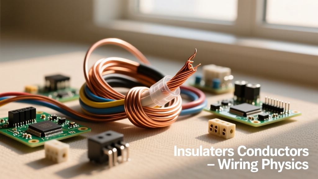

Every electrical circuit, from a simple DIY LED project to a massive industrial power grid, relies on a fundamental physical tug-of-war. On one side, we have materials that desperately want to move electrons; on the other, materials that fiercely resist that movement. Understanding the relationship between insulators and conductors is not just academic theory—it is the bedrock of electrical safety, wire sizing, and component selection.
The Atomic Battle: Free Electrons vs. Bound Electrons
To truly grasp how electricity flows, we have to look at the atomic level. According to the Bohr model of the atom, electrons orbit a central nucleus in distinct shells. The outermost shell, known as the valence shell, dictates how a material interacts with electricity.
In conductors, the valence shell contains only one to three electrons. These electrons are loosely bound to the nucleus. When a voltage (electrical pressure) is applied, these 'free electrons' easily detach and drift from atom to atom, creating an electrical current. This is often referred to as the 'electron sea' model.
In insulators, the valence shell is nearly full, typically holding five to eight electrons. These electrons are tightly bound to the nucleus and require a massive amount of energy to break free. Because the electrons cannot move freely, current cannot flow. As noted by the Georgia State University HyperPhysics database, the energy gap between the valence band and the conduction band in insulators is exceptionally wide, effectively blocking electron flow under normal conditions.
What Makes a Material a Conductor?
Not all conductors are created equal. The efficiency with which a material allows electron flow is measured by its electrical conductivity. In the wiring industry, we use the International Annealed Copper Standard (IACS) as a baseline benchmark, where pure annealed copper is assigned a conductivity of 100%.
The IACS Standard and Real-World Metals
- Silver (105% IACS): The most conductive natural element. However, its high cost and tendency to tarnish (creating silver sulfide) limit its use to specialized RF applications, high-end audio contacts, and aerospace electronics.
- Copper (100% IACS): The undisputed king of DIY and commercial wiring. It offers an optimal balance of high conductivity, tensile strength, and solderability. According to the NIST Engineering Physics Division, copper's predictable resistance over temperature gradients makes it the standard for calculating voltage drop.
- Gold (70% IACS): Gold is actually a poorer conductor than copper or silver. So why is it used in microcontrollers and PCB edge connectors? Gold is virtually immune to oxidation and corrosion. In low-voltage digital logic (like 3.3V or 5V microcontroller pins), even a microscopic layer of copper oxide can block the signal. Gold ensures a flawless, low-resistance connection over decades.
Copper vs. Aluminum: The DIY Wiring Debate
Aluminum sits at roughly 61% IACS. While it is a worse conductor than copper, it is significantly lighter and cheaper. This makes it the standard for heavy-gauge service entrance cables (e.g., 4/0 AWG aluminum for a 200A residential panel). However, aluminum presents unique physical challenges:
- Thermal Creep: Aluminum expands and contracts more than copper under heat cycles, which can cause terminal screws to loosen over time, leading to high-resistance arcing faults.
- Oxidation: Aluminum oxide forms instantly when the metal is exposed to air. Unlike copper oxide, which is somewhat conductive, aluminum oxide is a stubborn insulator. When terminating aluminum wire, you must use an anti-oxidant compound like Noalox to break down the oxide layer and prevent overheating.
The Role of Insulators: Containing the Current
If conductors are the highways for electrons, insulators are the guardrails. Their primary job is to confine the current to the intended path and protect users from shock. But insulators also serve a secondary, equally vital role: they prevent adjacent conductors from short-circuiting.
The effectiveness of an insulator is measured by its dielectric strength, typically expressed in kilovolts per millimeter (kV/mm). This is the maximum electric field the material can withstand before it experiences 'dielectric breakdown'—a catastrophic failure where the insulator violently becomes a conductor.
Always remember: An insulator is only an insulator up to its dielectric breakdown voltage. Beyond that threshold, the atomic bonds shatter, and the material becomes a conductor, often resulting in an arc flash or fire.
PVC vs. XLPE: Choosing the Right Jacket
In modern wire manufacturing, the choice of insulation material dictates where the wire can be safely installed.
- PVC (Polyvinyl Chloride): Used in standard THHN (Thermoplastic High Heat-resistant Nylon-coated) wire. PVC is cheap, flexible, and has a dielectric strength of roughly 40 kV/mm. However, it softens at higher temperatures and is generally limited to 75°C or 90°C depending on the environment.
- XLPE (Cross-Linked Polyethylene): Used in XHHW (Cross-linked Polyethylene High Heat-resistant Water-resistant) wire. The chemical cross-linking process turns the plastic into a thermoset material. XLPE will not melt or deform under extreme heat, allowing for higher ampacity ratings and superior resistance to moisture and chemical solvents.
Semiconductors: The Middle Ground
Between the extreme conductivity of copper and the extreme resistance of glass lies the semiconductor. Materials like silicon and germanium have exactly four valence electrons. In their pure state, they act as insulators. However, by 'doping' them with trace amounts of elements that have three or five valence electrons, we can precisely control their conductivity. This ability to switch between acting as an insulator and a conductor is the foundational physics behind MOSFETs, transistors, and every microcontroller you use in your DIY electronics projects.
Material Comparison Chart: Conductivity and Breakdown Voltage
| Material | Type | Conductivity (S/m) | Dielectric Strength (kV/mm) | Common Application |
|---|---|---|---|---|
| Silver | Conductor | 6.30 x 10^7 | N/A | High-frequency RF contacts |
| Copper | Conductor | 5.96 x 10^7 | N/A | Standard branch circuit wiring |
| Aluminum | Conductor | 3.77 x 10^7 | N/A | Service entrance feeders |
| XLPE | Insulator | ~10^-15 | ~50 | Underground and wet-location wire |
| PVC | Insulator | ~10^-14 | ~40 | Standard indoor THHN jacket |
| Mica | Insulator | ~10^-11 | ~118 | High-temp heating elements |
Real-World Troubleshooting: When Insulators Fail
In the field, the boundary between an insulator and a conductor can degrade. As an DIY electrician or electronics hobbyist, recognizing these failure modes is critical for safety.
Megger Testing and Carbon Tracking
Standard multimeters output only a few volts when measuring resistance, which is insufficient to test the true integrity of wire insulation. To properly test insulators, professionals use a Megohmmeter (commonly called a 'Megger'). This device injects high-voltage DC (typically 500V or 1000V) into the wire to measure leakage current through the insulation jacket. A healthy THHN wire will read in the hundreds of megohms; a degraded wire might drop into the kilohm range, indicating imminent failure.
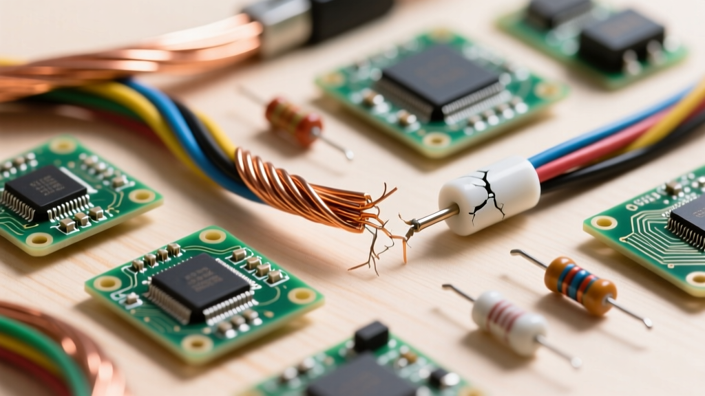
Another common failure mode is carbon tracking. When an insulator is exposed to moisture, dust, and continuous high voltage, microscopic leakage currents can burn tiny, conductive carbon paths into the surface of the plastic or ceramic. Once a carbon track forms, the insulator has effectively created its own internal conductor, leading to short circuits even if the bulk material remains intact. This is why high-voltage PCBs and components require conformal coating and adequate creepage distances, as outlined in the NFPA National Electrical Code safety standards.
Summary for the DIY Electrician
Mastering the concepts of insulators and conductors goes far beyond memorizing definitions. It means understanding why you must strip exactly 3/4-inch of PVC without nicking the copper, why aluminum requires specific anti-oxidant pastes, and why a wire rated for 90°C in a dry location might need to be derated if run through a damp, insulated wall. By respecting the atomic physics of the materials you work with, you ensure your circuits are not just functional, but inherently safe and built to last.