
The Core Insulator Definition in Electricity
When you strip a piece of standard THHN copper wire to make a connection, you are interacting with the two most fundamental categories of electrical materials: the conductor and the insulator. While the copper core is designed to facilitate the effortless flow of electrical current, the colored plastic jacket serves a completely opposite, yet equally vital, purpose. But what is the exact insulator definition in electricity?
In electrical engineering and physics, an insulator is defined as a material whose internal electric charges do not flow freely. Unlike conductors, which possess a 'sea' of free valence electrons that can easily drift when a voltage is applied, insulators hold their electrons in tight atomic bonds. This resistance to electron flow is what prevents short circuits, protects users from lethal shocks, and ensures that electrical energy is directed exactly where it needs to go. According to Energy Education (University of Calgary), the defining characteristic of an electrical insulator is its extremely high resistivity, typically measured in the trillions of ohm-meters.
Visualizing the Atomic 'Band Gap'
To truly understand why materials like rubber, glass, and PVC act as insulators, we have to look at quantum mechanics and atomic band theory. In solid-state physics, electrons exist in specific energy levels called 'bands.' The two most important bands for electrical conductivity are the valence band (where electrons are bound to atoms) and the conduction band (where electrons are free to move and carry current).
In conductors like copper, these two bands overlap, meaning electrons require almost zero extra energy to move and create a current. In insulators, however, there is a massive energy void between these two bands known as the Band Gap. As detailed by Georgia State University's HyperPhysics, the band gap in insulators is typically greater than 5 electron-volts (eV). Because standard electrical voltages cannot provide enough energy to push electrons across this massive 5+ eV gap, the electrons remain trapped in their valence bonds, and no current flows.
Material Breakdown: Dielectric Strength and Real-World Applications
Not all insulators are created equal. In DIY electronics and residential wiring, selecting the correct insulating material is just as critical as selecting the correct wire gauge. The primary metric used to compare insulators is dielectric strength, which measures the maximum electric field a material can withstand before it loses its insulating properties and begins to conduct. Dielectric strength is typically measured in kilovolts per millimeter (kV/mm).
Below is a comparison chart of common electrical insulators you will encounter in wiring, electronics, and high-voltage applications:
| Insulating Material | Dielectric Strength (kV/mm) | Max Operating Temp (°C) | Common Electrical Applications |
|---|---|---|---|
| Polyvinyl Chloride (PVC) | 15 - 40 | 70°C - 105°C | Standard household wiring (THHN/THWN), basic hook-up wire |
| Cross-linked Polyethylene (XLPE) | 20 - 50 | 90°C - 125°C | Underground feeder cables, solar PV wire, automotive wiring |
| PTFE (Teflon) | 60 - 100 | 260°C | Aerospace wiring, high-temp soldering sleeves, thermocouple wire |
| Alumina Ceramic | 10 - 35 | 1000°C+ | High-voltage transmission line standoffs, spark plug insulators |
| Mica | 40 - 150 | 500°C+ | Vintage electronics, heating element insulation, high-power capacitors |
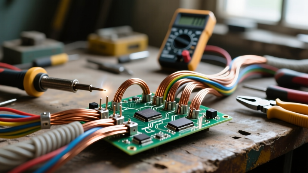
Pro-Tip for DIYers: If you are soldering in tight spaces and frequently melt the insulation on your wires, switch from standard PVC-jacketed wire to PTFE (Teflon) wire. PTFE's 260°C melting point means it will easily survive the tip of a soldering iron, whereas PVC will shrink, burn, and release toxic hydrochloric gas at much lower temperatures.
When Protection Fails: 3 Real-World Insulator Breakdown Modes
A common misconception among beginners is that insulators are impenetrable barriers. In reality, every insulator has a breaking point. When an insulator is subjected to conditions beyond its physical or electrical limits, it fails. Understanding these failure modes is critical for troubleshooting and ensuring long-term safety in your electrical projects.
1. Dielectric Breakdown (The Avalanche Effect)
If the voltage applied across an insulator exceeds its dielectric strength, the electric field becomes so intense that it literally rips electrons away from their parent atoms. This creates a chain reaction known as an electron avalanche. The material temporarily becomes a conductor, resulting in a spark or arc that physically punctures and carbonizes the insulator. Once carbonized, the material is permanently damaged and will remain conductive even after the voltage is removed.
2. Surface Tracking and Dendritic Growth
Sometimes the insulator itself doesn't fail, but the surface does. In environments with high humidity, dust, or corrosive flux residue (common in poorly cleaned DIY printed circuit boards), a conductive path can form on the surface of the insulator. Over time, micro-arcs burn tiny, branching carbon paths called dendrites across the surface. This 'tracking' eventually creates a dead short between two isolated conductors.
3. Thermal Degradation and Embrittlement
Insulators are highly susceptible to heat. If you run 14 AWG THHN wire (rated for 90°C in a dry location) through an attic that reaches extreme temperatures, or bundle too many current-carrying conductors together without applying NFPA 70 (National Electrical Code) derating factors, the insulation will overheat. Thermal degradation causes plasticizers to leach out of PVC, making the jacket brittle. Brittle insulation cracks when the wire is bent, exposing bare copper and creating an immediate shock and fire hazard.
The 'Air Gap' Exception
It is vital to remember that gases, including the air we breathe, are also insulators. Dry air has a dielectric strength of approximately 3 kV/mm. This is why electricity doesn't just arc across the room from a standard 120V wall outlet. However, when voltages climb into the thousands—such as in a car's ignition coil, a bug zapper, or a lightning strike—the voltage easily overcomes the 3 kV/mm barrier of the air gap, ionizing the gas and creating a conductive plasma channel (a spark). This principle is deliberately utilized in spark plugs and high-voltage switchgear.
Practical Wire Sizing and Insulation Selection for Beginners
Applying the insulator definition in electricity to your actual DIY projects means matching the insulation type to the environment, not just the voltage. Here is a practical decision framework for your next wiring project:
- Standard Indoor Branch Circuits: Use THHN/THWN-2. The PVC jacket with a nylon outer skin provides excellent abrasion resistance for pulling through PVC conduit, and it is rated for wet or dry locations up to 90°C (though breakers are usually terminated at 75°C limits).
- Outdoor and Direct Burial: Use UF-B (Underground Feeder) or XHHW-2. UF-B features a solid, moisture-resistant PVC jacket that encapsulates the wires, protecting them from soil acidity and moisture ingress that would otherwise degrade standard THHN.
- High-Temp Electronics & Motors: Use Silicone-jacketed wire or Fiberglass braided sleeves. Silicone remains highly flexible even at extreme temperatures and will not melt if it briefly touches a hot motor casing or exhaust manifold.
- High-Frequency/RF Signals: Use Coaxial cables with PTFE or Foam-PE dielectrics. The insulator in RF cables isn't just for safety; it maintains a precise physical distance between the center conductor and the shield to maintain a specific characteristic impedance (usually 50 or 75 ohms).
Testing Insulation Integrity: Beyond the Multimeter
A standard digital multimeter (DMM) is generally inadequate for testing the health of an insulator. A DMM typically applies less than 3 volts to measure resistance. While a DMM might show 'OL' (Open Loop) on a degraded wire, it cannot detect micro-fractures or moisture trapped inside the insulation jacket that will eventually fail under full line voltage.
To truly test insulation, professionals use a Megohmmeter (commonly known as a Megger). This device injects high DC voltage (typically 250V, 500V, or 1000V) into the wire to stress the insulation and measure the leakage current in mega-ohms or giga-ohms. If you are buying an older home or troubleshooting a motor that keeps tripping the breaker, a Megger test will reveal if the wire insulation has broken down internally, long before it causes a catastrophic short circuit.
Summary
Understanding the insulator definition in electricity goes far beyond memorizing a textbook phrase. It requires an appreciation of atomic band gaps, material science, and environmental stressors. Whether you are selecting PTFE wire for a high-temperature DIY drone build, or pulling THHN through conduit for a new workshop subpanel, respecting the limits of your insulating materials is the cornerstone of safe, reliable, and professional electrical work. Always verify your material's dielectric strength, respect its thermal limits, and never assume an insulator is invincible.