
Defining the Flow: What Is the Direct Current in Practical Terms?
When beginners ask, what is the direct current, the standard textbook answer is that it is the unidirectional flow of electric charge. Unlike alternating current (AC), which periodically reverses direction, direct current (DC) maintains a constant polarity. However, for electrical DIYers, solar installers, and automotive technicians, understanding DC goes far beyond a simple definition. It requires mastering the mathematics of low-voltage, high-current environments where wire sizing and voltage drop dictate system survival.
In a DC circuit, electrons flow continuously from the negative terminal to the positive terminal (electron flow), while conventional current models the flow from positive to negative. For all practical calculations regarding wire sizing and power consumption, we rely on conventional current. According to Fluke's electrical fundamentals guide, DC is the foundational power source for everything from microcontrollers and LED arrays to off-grid solar battery banks and EV powertrains.
The Core DC Calculation Framework (Ohm’s & Watt’s Law)
Before sizing a wire, you must calculate the exact current draw. DC circuits rely heavily on Watt's Law and Ohm's Law. Because DC voltage is typically fixed (e.g., a 12V lead-acid battery or a 24V lithium iron phosphate bank), the current (Amperes) scales inversely with the voltage when power (Watts) is constant.
- Watt's Law: Power (P) = Voltage (V) × Current (I)
- Ohm's Law: Voltage (V) = Current (I) × Resistance (R)
- Derived Current Formula: I = P / V
Expert Insight: In 12V DC systems, a 1,000W inverter doesn't just draw 83 amps. Accounting for inverter inefficiency (typically 85-90%), the actual draw from the battery is closer to 93-98 amps. Always calculate based on the input power, not the output rating.
Calculating DC Current Draw for Common DIY Loads
Let us look at a data table of common 12V DC loads to understand how quickly amperage accumulates in low-voltage systems.
| Device / Load | Wattage (W) | Nominal Voltage (V) | Calculated Current (A) | Recommended Wire (Short Run) |
|---|---|---|---|---|
| 5050 SMD LED Strip (5m) | 72W | 12V | 6.0A | 14 AWG |
| RV Diaphragm Water Pump | 96W | 12V | 8.0A | 12 AWG |
| 12V Compressor Fridge | 60W | 12V | 5.0A | 14 AWG |
| 2000W Pure Sine Inverter | 2200W (Input) | 12V | 183.3A | 2/0 AWG |
DC Voltage Drop: The Hidden Wire Sizing Killer
The most critical difference between AC and DC wiring calculations is the tolerance for voltage drop. A 3% voltage drop on a 120V AC circuit results in a loss of 3.6V, leaving 116.4V at the load—perfectly acceptable for most appliances. A 3% drop on a 12V DC system leaves only 11.64V. Many sensitive DC electronics, such as lithium BMS controllers or RV water pump pressure switches, will trigger low-voltage disconnects or fail to start at this threshold.
The All About Circuits DC textbook emphasizes that resistance in the conductor acts as a series voltage divider. To calculate DC voltage drop, we use the circular mil formula:
VD = (2 × K × I × L) / CM
- VD: Voltage Drop
- 2: Multiplier for the total loop length (positive and negative conductors)
- K: Resistivity of the conductor (12.9 ohms-cmil/ft for copper at 75°C)
- I: Current in Amperes
- L: One-way length of the wire in feet
- CM: Circular Mils of the wire cross-section
Step-by-Step DC Voltage Drop Calculation: The RV Water Pump Scenario
Imagine you are wiring a 12V, 8A RV water pump located 20 feet away from the DC distribution panel. You initially choose 12 AWG wire.
- Identify CM: 12 AWG copper wire has a cross-sectional area of 6,530 Circular Mils.
- Plug into formula: VD = (2 × 12.9 × 8 × 20) / 6530
- Calculate numerator: 2 × 12.9 × 8 × 20 = 4,128
- Divide by CM: 4,128 / 6,530 = 0.63V drop
- Calculate percentage: (0.63V / 12V) × 100 = 5.25%
Failure Mode Analysis: A 5.25% drop exceeds the recommended 3% limit for critical DC branch circuits. Furthermore, water pumps experience a startup surge (locked rotor amperage) that can be 2.5 times the running current. An 8A pump might draw 20A for a fraction of a second upon startup. At 20A, the voltage drop on 12 AWG wire spikes to 1.58V (13.1%), which will severely dim cabin lights on the same bus and may cause the pump motor to stall and overheat. Correction: Upgrade to 8 AWG wire (16,510 CM) to drop the running VD to 0.25% and handle the surge safely.
Circular Mil Area (CMA) Calculations for DC Conductors
Because DC current utilizes the entire cross-sectional area of a conductor uniformly, calculating the exact Circular Mil Area (CMA) is vital. Unlike AC circuits, which suffer from the "skin effect" (where high-frequency alternating current travels primarily on the outer edge of the wire), DC flows through the core. Therefore, stranded and solid DC wires of the same AWG have identical current-carrying capacities, though stranded is preferred for vibration resistance in automotive and marine applications.
| AWG Size | Circular Mils (CM) | DC Resistance (Ω/1000 ft at 75°C) | Max Ampacity (90°C Insulation) |
|---|---|---|---|
| 16 AWG | 2,580 | 5.08 | 14A |
| 14 AWG | 4,110 | 3.19 | 20A |
| 12 AWG | 6,530 | 2.01 | 25A |
| 10 AWG | 10,380 | 1.26 | 35A |
| 8 AWG | 16,510 | 0.79 | 50A |
| 4 AWG | 41,740 | 0.31 | 85A |
Note: Ampacity ratings are based on NEC Table 310.16 for single conductors in free air or standard raceways. Always consult the Copper Development Association guidelines for specific installation derating factors.
Real-World DC Troubleshooting & Measurement
Understanding what is the direct current theoretically is only half the battle. In the field, DC systems frequently fail due to poor termination rather than undersized wire. DC current is highly sensitive to contact resistance.
The Thermal Runaway of Loose DC Connections
When a DC lug is not crimped with adequate force, or a busbar bolt is under-torqued, micro-arcing and contact resistance occur. Because P = I²R, even a tiny increase in resistance (R) at a joint carrying 50A of DC current generates massive localized heat. This heat oxidizes the copper, which further increases resistance, creating a destructive feedback loop known as thermal runaway.
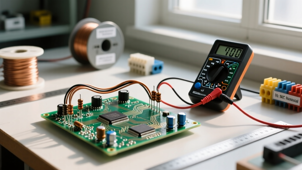
- Diagnostic Step 1: Use a digital multimeter (DMM) to measure the voltage directly at the battery terminals under load.
- Diagnostic Step 2: Measure the voltage at the load terminals while the load is active.
- Diagnostic Step 3: If the difference exceeds your calculated wire VD, use an infrared thermal camera to scan all intermediate fuses, breakers, and crimps. A hot spot indicates a failing mechanical connection, not a wire sizing issue.
By combining the foundational definition of DC with rigorous voltage drop mathematics and circular mil calculations, DIYers can design low-voltage systems that are not only functional on day one but remain safe and efficient over years of continuous operation.