
The Atomic Root: Band Theory and Electron Mobility
To truly understand the difference between conductor and insulator of electricity, we must look past the macroscopic wire and examine the atomic lattice. The behavior of any material in an electrical circuit is dictated by its electronic band structure—specifically, the relationship between the valence band (where electrons are bound to atoms) and the conduction band (where electrons are free to move and carry current).
In conductors, such as Oxygen-Free High Conductivity (OFHC) copper or silver, the valence and conduction bands overlap. There is zero band gap. This means that even at room temperature, a massive sea of free electrons is available to drift through the lattice when an electromotive force (voltage) is applied. This overlapping band structure is why copper boasts a conductivity of approximately 5.96 × 10^7 Siemens per meter (S/m).
Conversely, insulators possess a massive band gap—typically greater than 3 to 5 electron volts (eV). According to Georgia State University's HyperPhysics database on solid-state band theory, this wide gap prevents valence electrons from jumping into the conduction band under normal thermal or electrical stress. Materials like Cross-linked Polyethylene (XLPE) and Polytetrafluoroethylene (PTFE/Teflon) tightly bind their electrons, effectively blocking current flow and confining the electrical energy strictly to the conductor.
Comprehensive Material Reference Chart
When designing wiring harnesses, selecting PCB traces, or routing mains power, engineers must balance conductivity against dielectric strength. The table below contrasts common conductive metals with standard dielectric insulation materials used in modern electrical infrastructure.
| Material | Category | Primary Metric (Conductivity / Dielectric Strength) | Max Continuous Temp | Common Application |
|---|---|---|---|---|
| Silver (Ag) | Conductor | 6.30 × 10^7 S/m | 961°C (Melting) | High-end audio contacts, RF relays |
| Copper (Cu) | Conductor | 5.96 × 10^7 S/m | 1085°C (Melting) | Standard AWG wiring, PCB traces, busbars |
| Aluminum (AA-8000) | Conductor | 3.77 × 10^7 S/m | 660°C (Melting) | Heavy feeder cables, overhead transmission |
| PVC (Polyvinyl Chloride) | Insulator | ~40 kV/mm | 60°C - 105°C | Consumer electronics, standard THHN wire |
| XLPE (Cross-linked PE) | Insulator | ~50 kV/mm | 90°C (250°C short-circuit) | Medium/High voltage underground cables |
| PTFE (Teflon) | Insulator | 60 - 100 kV/mm | 260°C | Aerospace wiring, high-temp soldering sleeves |
| Mica | Insulator | ~118 kV/mm | 500°C+ | Industrial heaters, high-voltage capacitors |
Dielectric Breakdown: When Insulators Become Conductors
The functional difference between conductor and insulator of electricity is not absolute; it is highly dependent on environmental and electrical stress. When an insulator is subjected to an electric field that exceeds its dielectric strength, it undergoes dielectric breakdown.
During this event, the intense electromagnetic force literally tears electrons from their atomic bonds, creating a sudden, catastrophic avalanche of free carriers. The insulator momentarily becomes a conductor, resulting in an arc flash, short circuit, or puncture through the material. For example, while standard PVC insulation on a 12 AWG THHN wire is rated for 600V, applying a 15,000V transient surge will easily exceed its ~40 kV/mm dielectric threshold (assuming a 0.76mm insulation thickness), causing immediate puncture.
In high-voltage engineering, partial discharge and the corona effect slowly degrade insulation long before total breakdown occurs. Ionized air around a poorly terminated conductor generates ozone and nitric acid, which chemically attack organic insulators like rubber and PVC, turning them brittle and ultimately destroying their insulating properties.
Thermal Limits: Annealing and Plasticizer Migration
Temperature profoundly alters the physical boundary between conductors and insulators. Heat introduces lattice vibrations (phonons) that impede electron flow in conductors while simultaneously accelerating chemical degradation in insulators.
Conductor Annealing and Resistance Drift
While copper will not melt until 1085°C, it begins to anneal (soften and lose tensile strength) at temperatures as low as 200°C. More critically, for every 1°C rise in temperature, copper's electrical resistance increases by roughly 0.393%. In high-current DIY battery builds or solar arrays, undersized conductors generate excessive I²R heat, raising resistance, which generates more heat—a thermal runaway loop that can compromise the entire circuit.
Insulator Plasticizer Migration
Organic insulators like PVC rely on chemical plasticizers to remain flexible. When operated continuously near their thermal limits (e.g., 105°C), these plasticizers migrate to the surface and evaporate. The insulation shrinks, cracks, and exposes the bare conductor. This is why the NFPA 70 National Electrical Code (NEC) strictly mandates specific temperature derating curves when bundling multiple current-carrying conductors in a single raceway; the trapped heat accelerates insulation failure.
Semiconductors: The Engineered Middle Ground
No reference guide is complete without acknowledging semiconductors like Silicon (Si) and Germanium (Ge). These materials possess a narrow band gap (around 1.1 eV for Silicon). At absolute zero, they act as perfect insulators. However, at room temperature—or when doped with specific impurities like phosphorus or boron—their conductivity can be precisely engineered. This controllable transition between insulating and conducting states is the foundational physics behind every MOSFET, diode, and microcontroller you solder onto your PCBs.
Field Testing: Verifying Insulation Integrity
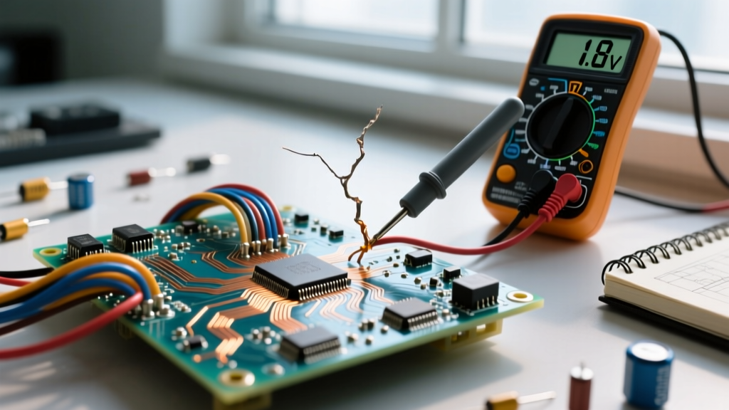
You cannot rely on visual inspection to verify the difference between conductor and insulator of electricity in aging infrastructure. Micro-fractures and moisture ingress compromise dielectric strength invisibly. Professional electricians and maintenance engineers use a Megohmmeter (Megger) to perform Insulation Resistance (IR) testing.
Pro-Troubleshooting Framework: When testing a 480V industrial motor winding, apply 1000VDC via the Megohmmeter. Record the resistance at 1 minute and 10 minutes. Divide the 10-minute reading by the 1-minute reading to calculate the Polarization Index (PI). A PI of less than 1.0 indicates dangerous moisture contamination or severe insulation degradation, meaning the insulator is on the verge of becoming a conductive path to ground.
By understanding the deep atomic physics, thermal limitations, and failure modes of both conductive and dielectric materials, DIYers and master electricians alike can design safer, more resilient electrical systems that stand the test of time and environmental stress.