
Decoding the Home Electrical Wiring Diagram
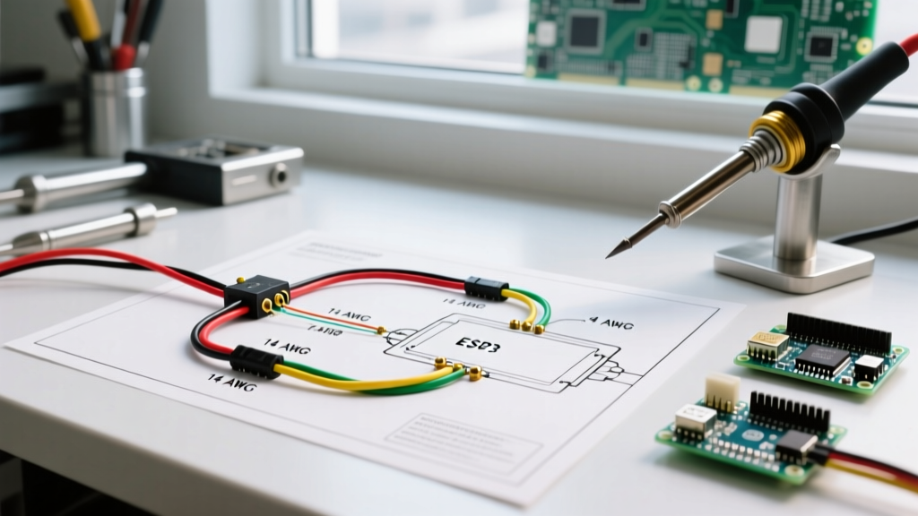
A residential home electrical wiring diagram is far more than a simple map of connections; it is a strict blueprint governed by thermal limits, voltage drop calculations, and the National Electrical Code (NEC). Whether you are adding a dedicated 240V circuit for an EV charger or rewiring a kitchen for modern appliance loads, misinterpreting the gauge and color specifications on your schematic can lead to nuisance tripping, melted insulation, or catastrophic electrical fires.
In 2026, with the increased integration of smart home panels and high-draw induction appliances, understanding the exact wire gauge and color coding standards is non-negotiable. This reference guide breaks down the critical data you need to read, interpret, and execute your residential wiring diagrams safely and legally.
The Standard NEC Wire Color Code Reference
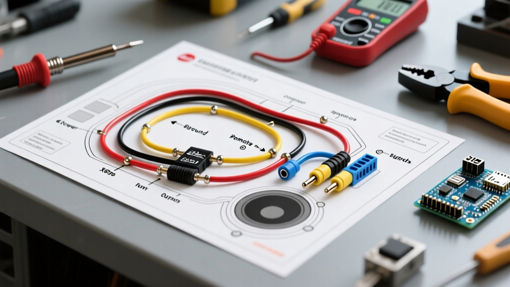
Before pulling any cable through a stud bay, you must verify that the physical wire colors match the schematic's legend. The NEC strictly mandates specific color assignments to prevent cross-phasing and accidental grounding faults. While a home electrical wiring diagram will typically label conductors as L1, L2, N, and G, the physical insulation must adhere to the following standards:
| Insulation Color | Function | Common Residential Applications | NEC Schematic Symbol |
|---|---|---|---|
| Black | Hot (Ungrounded) | Standard 120V branch circuits, switch legs | L1 or Line |
| Red | Hot (Secondary) | 240V appliances, 3-way switch travelers, smoke detector interconnects | L2 or T1 |
| Blue / Yellow | Hot (Tertiary) | Multi-way switching, conduit pulls for dedicated 20A/30A circuits | L3 or T2 |
| White / Gray | Neutral (Grounded) | Return path for 120V circuits, balanced 240V loads | N or Neutral |
| Bare / Green | Equipment Ground | Fault current path, bonding metal boxes and appliance chassis | G or Ground |
Pro-Tip on Switch Loops: If your home electrical wiring diagram shows a white wire being used as a 'hot' traveler or switch leg, NEC 200.6(C) requires you to permanently mark the white insulation with black or red electrical tape (or paint) at both termination points. Never assume a white wire is neutral inside a switch box without verifying the schematic.
Wire Gauge vs. Ampacity: Sizing Your Conductors
The American Wire Gauge (AWG) system is inverse: the lower the number, the thicker the wire and the higher the current it can safely carry. When reviewing a wiring diagram, the specified breaker size dictates the minimum wire gauge. However, a critical mistake many DIYers make is referencing the 90°C ampacity column for THHN wire when terminating at standard residential breakers.
The NEC 110.14(C) Temperature Rule
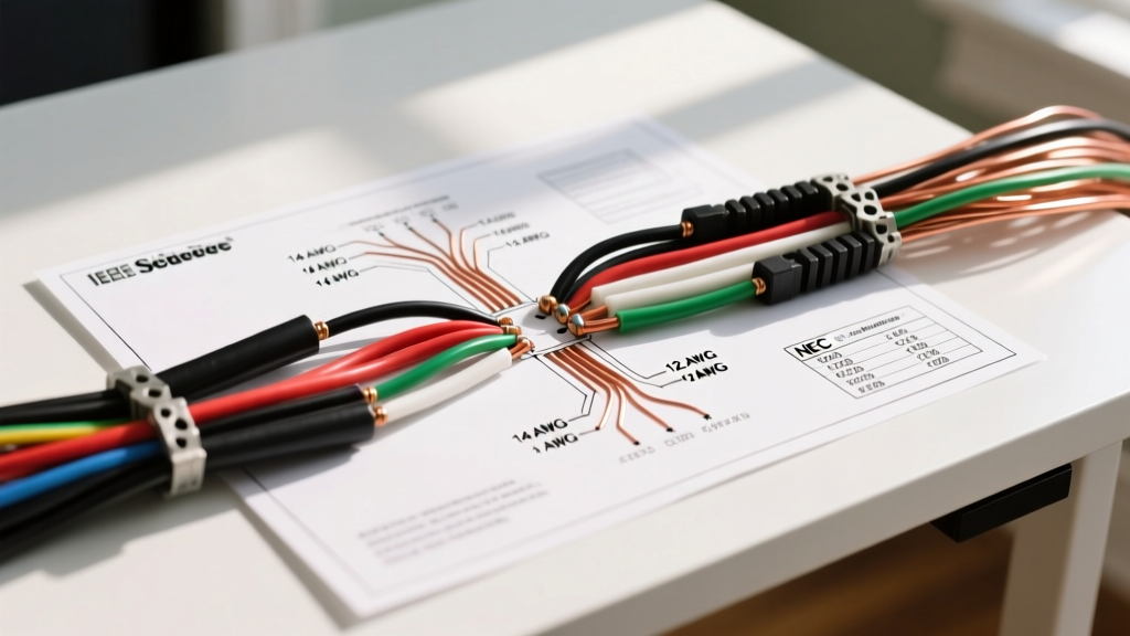
According to the National Fire Protection Association (NFPA) 70: National Electrical Code, circuits rated 100 amps or less, or utilizing conductors sized 14 AWG through 1 AWG, must be sized using the 60°C ampacity column, regardless of the wire's 90°C insulation rating. This is because standard residential breaker terminals (like Square D QO or Eaton BR) are typically rated for 75°C, and the weakest link in the thermal chain dictates the safety limit.
Residential Ampacity & Breaker Sizing Chart (Copper)
The following table reflects standard copper conductor sizing for residential branch circuits and feeders, adhering to the 60°C termination rule for standard breakers:
| Wire Gauge (AWG) | Max Ampacity (60°C) | Max Breaker Size | Typical Home Application | Approx. 2026 Cost (250ft NM-B) |
|---|---|---|---|---|
| 14 AWG | 15 Amps | 15A | Lighting, general living room receptacles | $85 - $95 |
| 12 AWG | 20 Amps | 20A | Kitchen/Dining receptacles, bathroom GFCI | $115 - $135 |
| 10 AWG | 30 Amps | 30A | Dryers, water heaters, heavy window ACs | $180 - $210 |
| 8 AWG | 40 Amps | 40A | Electric ranges, Level 2 EV chargers (7.6kW) | $290 - $330 |
| 6 AWG | 55 Amps | 60A* | Subpanels, heavy EV chargers (11.5kW) | $420 - $480 |
| 4 AWG | 70 Amps | 70A | Large subpanels, tankless electric heaters | N/A (Typically THHN in conduit) |
| 2 AWG | 95 Amps | 100A | 100A Subpanel feeders, detached garages | N/A (Use SER Cable) |
*Note: While 6 AWG copper is rated for 55A at 60°C, NEC 240.4(B) allows the next standard breaker size up (60A) if the calculated load does not exceed 55A. For a true 60A continuous load, 4 AWG copper is required.
Interpreting Wire Types on Schematics
A comprehensive home electrical wiring diagram will specify the cable type, not just the gauge. Using the wrong jacket type violates code and creates severe fire hazards. Look for these abbreviations on your prints:
- NM-B (Non-Metallic Sheathed): Standard 'Romex'. Rated for 90°C but limited to 60°C ampacity. Must be used in dry, interior, protected spaces. Cannot be buried or exposed to UV.
- UF-B (Underground Feeder): Solid PVC jacket encapsulating the conductors. Rated for direct burial (minimum 24 inches deep without a raceway). Used for outdoor lighting, well pumps, and detached shed feeds.
- THHN / THWN-2: Individual conductors pulled through PVC or EMT conduit. Required for interior runs where NM-B is prohibited (e.g., above drop ceilings in commercial spaces, or long underground conduit runs).
- SER (Service Entrance Round): Heavy-duty, multi-conductor cable used for main panel feeders and large subpanels. In 2026, aluminum SER (like 4/0-4/0-2/0-4 AL) is the industry standard for 200A residential services due to copper price volatility, costing roughly $4.50 per foot compared to $18+ per foot for copper equivalents.
Voltage Drop: The Hidden Diagram Variable
Standard wiring diagrams rarely account for distance. If your diagram calls for a 20A circuit using 12 AWG wire, but the run from the panel to the farthest receptacle exceeds 90 feet, you will experience a voltage drop exceeding the recommended 3% limit. This causes motors to overheat and smart home hubs to reboot randomly.
To calculate voltage drop for single-phase residential circuits, use this formula:
VD = (2 × K × I × D) / CM
- K = 12.9 (for Copper)
- I = Current in Amps (e.g., 16A for an 80% continuous load on a 20A circuit)
- D = One-way distance in feet
- CM = Circular Mils of the wire (6530 for 12 AWG, 10380 for 10 AWG)
Example: A 150-foot run of 12 AWG copper carrying 16A yields a voltage drop of 5.9V (nearly 5% on a 120V circuit). To correct this, your execution of the wiring diagram must upgrade the conductor to 10 AWG (CM = 10380), dropping the loss to an acceptable 3.7V (3.1%). For extensive calculations, refer to the Cerro Wire Ampacity Tables and voltage drop calculators.
Common Mistakes When Reading Residential Diagrams
Even seasoned DIYers make critical errors when translating a home electrical wiring diagram into physical reality. Avoid these specific failure modes:
- Ignoring the Grounding Electrode Conductor (GEC): Diagrams for subpanels often omit the GEC, assuming it's part of the main service. A detached garage subpanel requires its own grounding rods and a 6 AWG or 4 AWG bare copper GEC tied to the local earth, independent of the neutral.
- Shared Neutrals (Multi-Wire Branch Circuits): If your diagram shows a 14/3 or 12/3 cable feeding two separate 120V circuits, this is an MWBC. You must use a 2-pole breaker or handle-tied single-pole breakers. Failing to do so means the neutral wire will carry the sum of both loads instead of the difference, leading to an immediate neutral meltdown and fire.
- Mixing Aluminum and Copper Terminations: When feeding a subpanel with Aluminum SER cable, you must use lugs rated for AL/CU and apply an anti-oxidant compound (like Noalox) to the stripped aluminum strands. Standard residential breakers are not rated for direct aluminum termination on branch circuits smaller than 8 AWG.
Frequently Asked Questions (FAQ)
Can I use 14 AWG wire on a 20A breaker if the load is low?
No. The Occupational Safety and Health Administration (OSHA) and NEC strictly prohibit this. The breaker protects the wire, not the appliance. A 20A breaker will allow enough current to pass through 14 AWG wire to ignite the surrounding wood framing before the breaker ever trips. Always match the wire gauge to the breaker's maximum rating (14 AWG = 15A max, 12 AWG = 20A max).
Why does my wiring diagram show a white wire connected to a black wire?
This indicates a switch loop. Power is being sent down to a wall switch via a 2-conductor cable (like 14/2 NM-B). The white wire is being repurposed as the always-hot feed to the switch, and the black wire returns the switched-hot power to the light fixture. As per NEC, the white wire must be re-identified with black tape at both ends to warn future electricians that it is carrying live voltage.
Do I need to upgrade my wire gauge for high-altitude or high-temperature attics?
Yes. If your NM-B cable is routed through an attic where ambient temperatures regularly exceed 86°F (30°C), you must apply temperature derating factors found in NEC Table 310.15(B)(16). In extreme attic heat (e.g., 113°F to 122°F), a 12 AWG wire's ampacity is multiplied by 0.58, effectively reducing its safe capacity to just 11.6 Amps. In these scenarios, you must upsize to 10 AWG or route the cables below the attic insulation line to maintain code compliance.