
The Hidden Cost of Oxidation in Modern Workspaces
Setting up a professional or advanced hobbyist electronics workbench in 2026 requires more than just a high-quality soldering station and a reliable fume extractor. One of the most frequently overlooked yet financially critical components of a complete workspace is the soldering tip tinner. Modern micro-soldering tips, such as the Weller RT1 series or Hakko T18 nano-tips, feature incredibly thin iron plating over a copper core to maximize thermal transfer. However, this thin plating is highly susceptible to oxidation and pitting. Replacing a single micro-tip can cost anywhere from $12 to $45. Over a year of daily use, failing to maintain your tip can add hundreds of dollars in unnecessary replacement costs to your overhead.
According to the IPC J-STD-001 standards for soldered electrical assemblies, proper tip maintenance and wetting are foundational to achieving reliable metallurgical bonds. A dry, oxidized tip acts as a thermal insulator, forcing the operator to apply excessive mechanical pressure and dwell time, which ultimately damages both the PCB pad and the tip itself. Integrating a dedicated soldering tip tinner into your daily workflow and physical workspace layout is the most effective defense against thermal degradation.
Anatomy of a Soldering Tip Tinner: Chemistry and Mechanics
To properly utilize a tip tinner, you must understand what is actually inside the tin. A high-quality soldering tip tinner is not simply a block of solder. It is a carefully engineered composite consisting of two primary elements:
- Solder Powder: Fine particulate solder (either Sn63/Pb37 for leaded applications or SAC305/Sn96.5Ag3.0Cu0.5 for lead-free compliance). The powder form provides a massive surface area for immediate thermal transfer and wetting.
- Flux Matrix: The powder is suspended in a mildly activated rosin (RMA) or a no-clean flux base. This flux is specifically formulated to reduce copper oxide and iron oxide at standard soldering temperatures (300°C to 350°C) without being so aggressive that it etches the tip's iron plating.
When an oxidized tip is plunged into the tinner, the flux matrix instantly boils and chemically strips the oxide layer. Simultaneously, the solder powder melts and alloys with the freshly exposed iron plating, creating a protective, shiny layer of fresh solder that prevents immediate re-oxidation when the iron is returned to its holder.
Workbench Ergonomics: Where to Place Your Tip Tinner
Physical placement of your soldering tip tinner on the workbench dictates how consistently you will use it. If it is out of reach, you will default to aggressive wiping on a brass sponge, which can cause thermal shock and micro-fractures in the tip plating.
The 'Golden Triangle' Setup
Ergonomic workspace design for soldering relies on a 'Golden Triangle' between the iron holder, the cleaning medium, and the workpiece. Your tip tinner should be positioned exactly halfway between your iron's resting holster and your primary work mat.
- Thermal Isolation: Always place the tinner tin on a high-temperature silicone mat (rated for at least 500°C). The bottom of the tin can easily exceed 150°C during prolonged use, which will scorch wooden desks or melt standard PVC desk mats.
- Fume Extractor Proximity: The flux in a tip tinner generates a sudden, dense burst of colophony smoke when activated. Position the tinner within the 12-to-18-inch capture radius of your fume extractor fan. However, do not place it directly under a high-velocity downdraft vent, as the constant airflow will prematurely dry out the volatile solvents in the flux matrix, turning your tinner into a useless brick.
- Left vs. Right-Handed Orientation: For right-handed operators, the tinner should sit at the 2 o'clock position relative to the iron stand. This allows a natural, fluid wrist rotation to dip and twist the tip without crossing over the workpiece and risking a drip of molten solder onto your PCB.
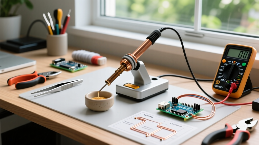
Pro-Tip for Micro-Soldering: If you are working with ultra-fine pitch components (0.4mm BGA or 01005 passives) and using a JBC Nano station, transfer a small pea-sized amount of tip tinner into a shallow ceramic dishing palette. Deep tins can sometimes cause micro-tips to bend if you accidentally strike the bottom or sides at the wrong angle.
The 4-Step Tinning Protocol for Maximum Longevity
Using a soldering tip tinner incorrectly can actually destroy your tip. Plunging a 420°C tip into a tinner will instantly carbonize the flux, creating a hard, black, glassy shell that is nearly impossible to remove. Follow this precise protocol for optimal results:
Step 1: Temperature Verification
Ensure your soldering station is set between 300°C and 330°C (572°F - 626°F). If you have been soldering at higher temperatures, allow the iron to cool to this range before tinning. The melting point of SAC305 is 217°C, and Sn63/Pb37 is 183°C; a 300°C tip provides more than enough thermal headroom to melt the powder without burning the flux.
Step 2: The Plunge and Twist
Insert the tip straight down into the tinner paste. Do not scrape the sides. Once submerged about 2-3mm, gently twist the iron 90 degrees clockwise, then 90 degrees counter-clockwise. This mechanical action, combined with the chemical flux, breaks up stubborn oxide crusts.
Step 3: The Dwell Time
Hold the tip in the paste for exactly 1.5 to 2 seconds. You will see a small amount of smoke and hear a faint sizzle. Any longer than 3 seconds, and the flux will begin to deplete and carbonize.
Step 4: The Gentle Wipe
Withdraw the tip and immediately perform a single, gentle wipe on a damp cellulose sponge or a slow pass through a brass wire sponge to remove the excess flux residue and any suspended oxide particles. The tip should now be mirror-bright and perfectly wetted. As noted in SparkFun's comprehensive soldering tutorials, leaving heavily fluxed residue on the tip while it rests in the holster can lead to long-term corrosive pitting.
2026 Market Comparison: Top Tip Tinners for Your Workspace
Not all tinners are created equal. The shift toward strict RoHS compliance in commercial repair and manufacturing means lead-free tinners are now the standard, though leaded options remain for specialized aerospace or legacy repair. Below is a comparison of the top three professional-grade soldering tip tinners available on the market.
| Product Model | Alloy Composition | Flux Type | Approx. Cost (2026) | Best Use Case |
|---|---|---|---|---|
| MG Chemicals 4901 | SAC305 (Lead-Free) | No-Clean / Mild Rosin | $14.00 (20g tin) | General SMD, RoHS-compliant repair labs, daily maintenance. |
| Chemtronics 40-100 | Sn96.5Ag3.0Cu0.5 | RMA (Rosin Mildly Activated) | $26.00 (50g jar) | Heavy oxidation recovery, high-volume manufacturing lines. |
| AIM Solder 256-TipTinner | Sn63/Pb37 (Leaded) | Activated Rosin | $18.00 (25g tin) | Legacy aerospace repair, vintage audio restoration, non-RoHS environments. |
For most modern electronics hobbyists and repair technicians, the MG Chemicals 4901 Lead-Free Tip Tinner offers the best balance of price, performance, and safety. Its no-clean flux matrix leaves a minimal, non-corrosive residue that won't interfere with sensitive RF circuits or high-impedance analog traces.
Troubleshooting: Failure Modes and Edge Cases
Even with proper setup, you may encounter issues with your tip tinner over time. Here is how to diagnose and resolve the most common workspace failures.
Failure Mode 1: The 'Black Crust' Carbonization
Symptom: The surface of the tinner paste develops a hard, black, glossy crust. The iron tip comes out black instead of shiny.
Cause: The iron temperature was too high (exceeding 380°C), or the dwell time was too long, causing the flux to burn into carbon.
Solution: Do not scrape the crust off with a metal tool, as this contaminates the tinner with iron shavings. Instead, use a wooden toothpick or a plastic spudger to gently flake off the top 2mm of the carbonized layer. The fresh, active paste underneath will be perfectly usable. Lower your station temperature moving forward.
Failure Mode 2: Flux Depletion and Dryness
Symptom: The paste looks dry, crumbly, and the solder powder does not melt smoothly onto the tip.
Cause: Prolonged exposure to air, or placement directly under a high-velocity fume extractor fan, has evaporated the volatile solvents in the flux.
Solution: You can temporarily rehydrate a dry tinner by adding 3-4 drops of high-quality liquid tacky flux (such as Amtech NC-559-V2-TF) into the tin and stirring it gently with a fiberglass scratch pen. However, if the solder powder itself has oxidized into a dull grey dust, the tinner is dead and must be replaced.
Failure Mode 3: Cross-Contamination
Symptom: Your solder joints are exhibiting dull, grainy textures, or you are experiencing wetting issues on lead-free boards after using the tinner.
Cause: You used a leaded tip tinner (Sn63/Pb37) on an iron that is subsequently used for lead-free (SAC305) assembly. Lead contamination in a lead-free process is a severe violation of IPC standards and compromises joint reliability.
Solution: Dedicate specific irons and specific tinners to either leaded or lead-free workflows. Color-code your tinner tins with high-temperature Kapton tape (e.g., Red for Leaded, Blue for Lead-Free) to prevent catastrophic workspace cross-contamination.
Conclusion: A Small Investment for Massive Returns
Integrating a high-quality soldering tip tinner into your workspace setup is not merely an accessory upgrade; it is a fundamental shift in how you manage thermal assets. By dedicating a specific, ergonomically sound zone on your workbench for tip maintenance, adhering to strict temperature protocols, and selecting the correct alloy for your specific soldering environment, you will drastically extend the lifespan of your tips. In an era where precision micro-soldering is the standard, protecting your iron's plating is just as important as the components you are soldering to the board.