
The Science of Polymer Thermal Welding
Learning how to plastic weld with a soldering iron is one of the most valuable repair skills in the modern DIY electronics and maker toolkit. Whether you are repairing a cracked RC car chassis, fixing a 3D printer enclosure, or restoring automotive interior trim, thermal plastic welding creates molecular bonds that are often stronger than the original injection-molded part. However, unlike soldering copper or tinning wires, plastics are highly unforgiving of thermal variance. A 20°C overshoot won't just ruin a joint; it will degrade the polymer chain and release toxic volatile organic compounds (VOCs).
To achieve structural integrity, you must understand the thermal thresholds of your specific polymer. According to the British Plastics Federation, every thermoplastic has a distinct glass transition temperature (Tg) and a melting/softening point. Applying heat beyond the degradation temperature causes irreversible chemical breakdown.
| Polymer | Glass Transition (°C) | Melt / Softening (°C) | Iron Target Temp (°C) | Degradation Risk |
|---|---|---|---|---|
| PLA | 60 - 65 | 150 - 160 | 180 - 200 | Low (brittle if overheated) |
| PETG | 80 - 85 | 220 - 250 | 250 - 270 | Medium (stringing/bubbling) |
| ABS | 105 | 210 - 240 | 260 - 280 | High (Styrene gas off-gassing) |
| Polycarbonate (PC) | 147 | 267 - 310 | 300 - 330 | Extreme (Requires specialized station) |
| Nylon (PA6) | 47 - 60 | 215 - 220 | 250 - 270 | Medium (Oxidation/discoloration) |
Hardware Setup: Tip Geometry and Station Selection
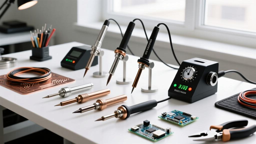
The most common mistake beginners make when attempting to plastic weld is using a standard conical or fine-point soldering tip. Conical tips lack the thermal mass and surface area required to transfer heat evenly into a polymer matrix, resulting in localized scorching and cold joints.
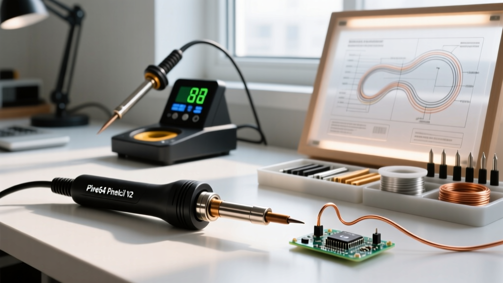
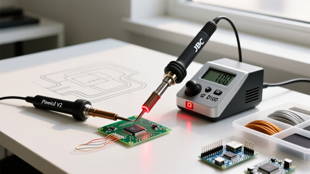
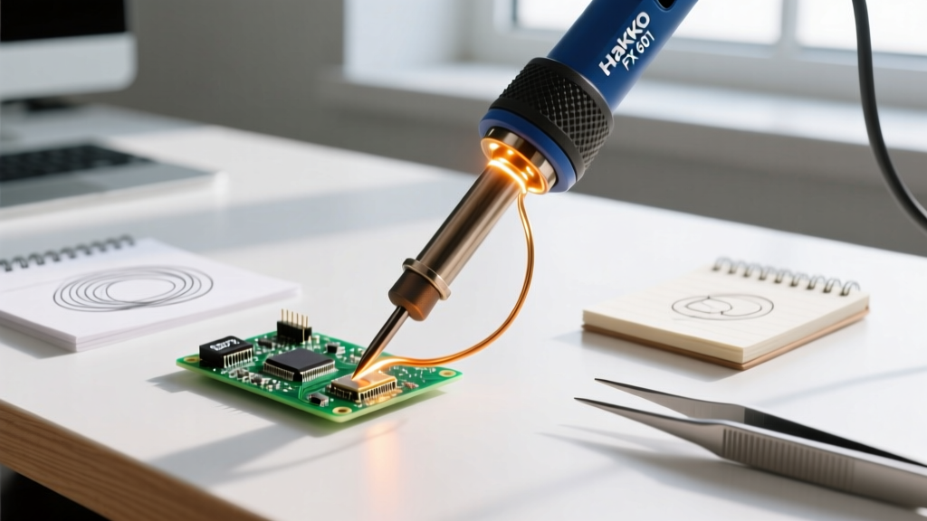
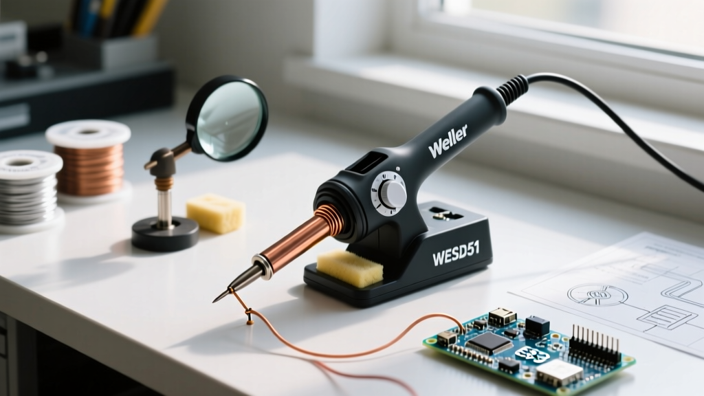
For plastic welding, you need a chisel, spatula, or custom-bent copper tip. The Hakko T18-D24 (a 2.4mm chisel tip) or the Pine64 Spatula tip for the Pinecil V2 are ideal. The flat surface area allows you to smooth the molten plastic pool while transferring heat efficiently. Furthermore, your soldering station must feature closed-loop temperature control. Ungrounded, mains-powered 'fire-sticks' will oscillate wildly in temperature and burn through thin plastic sheets instantly.
Calibrating the Hakko FX-888D for Plastics
Out of the box, the Hakko FX-888D may have a thermal offset of up to ±15°C due to ambient room conditions and tip wear. Because ABS degrades into styrene gas rapidly above 300°C, precise calibration is mandatory.
- Insert the T18-D24 chisel tip and turn the station OFF.
- Press and hold the UP arrow button while turning the power switch ON.
- The display will show the current sensor reading. Place a calibrated K-type thermocouple directly against the flat face of the chisel tip.
- Use the UP/DOWN arrows to match the station's display to your thermocouple's exact reading.
- Press and hold the ENTER button for 2 seconds to save the offset. The station will return to normal operation.
Calibrating the Pinecil V2 (IronOS)
If you are using a modern DC-powered iron like the Pinecil V2 running IronOS, calibration is handled via the digital menu.
- Navigate to Settings > Advanced Settings > Calibrate CJC (Cold Junction Compensation) with the tip installed but at room temperature.
- For high-temperature plastics like Polycarbonate, ensure your Power Limit is set appropriately for your power supply (e.g., 65W for a standard USB-C PD brick) to maintain thermal recovery during continuous welding.
- Set the Sleep Temperature to 150°C. This prevents the tip from degrading the plastic if you set it down momentarily, while keeping it close enough to the polymer's Tg to resume welding instantly.
Critical Safety: VOCs and Fume Extraction
Heating thermoplastics—particularly ABS and Polystyrene—releases hazardous VOCs, including styrene and carbon monoxide. According to the United States Environmental Protection Agency (EPA), indoor concentrations of VOCs can be significantly higher than outdoor levels, and localized heating of polymers creates concentrated toxic plumes.
⚠️ SAFETY DIRECTIVE: Never plastic weld in an unventilated room. You must use a localized fume extractor equipped with an activated carbon filter (such as the Hakko FA-400 or a DIY blower with dual-stage HEPA/Carbon media) positioned within 4 inches of the weld pool. Wear a half-face respirator with organic vapor (OV) cartridges if welding ABS or PC for extended periods.
The 4-Step Plastic Welding Execution Protocol
As detailed in advanced maker guides like those featured on Hackaday, a successful structural weld requires meticulous preparation and a specific sequence of thermal application.
Step 1: Joint Preparation and V-Grooving
Do not attempt to melt two flat edges together. Use a Dremel rotary tool or a deburring knife to carve a V-groove along the seam of the crack. The V-groove increases the surface area for the filler material to bond and creates a physical channel that prevents the filler from rolling off. Clean the groove thoroughly with 99% isopropyl alcohol to remove mold release agents and skin oils.
Step 2: Tack Welding and Alignment
Set your iron to the lower end of the polymer's melting range. Press the flat of the chisel tip across the crack at 2-inch intervals to create 'tack welds.' This holds the part in perfect alignment and prevents thermal warping during the main fill pass. Allow 30 seconds of cooling between tacks to prevent localized heat buildup.
Step 3: Filler Material Extrusion
Never weld a joint without adding filler material; melting the base material alone causes severe thinning and structural weakness.
- For 3D Printed Parts: Use 1.75mm filament of the exact same brand and color.
- For Injection Molded ABS: Cut strips from discarded LEGO bricks or use dedicated ABS welding rods.
- For HDPE (Milk Jugs/Buckets): Cut thin ribbons from scrap HDPE. Note that HDPE has high surface tension and will stick to standard copper tips. You must use a PTFE (Teflon) coated tip or wrap the tip in high-temp Kapton tape to prevent the molten HDPE from fusing to your iron.
Step 4: Smoothing and Annealing
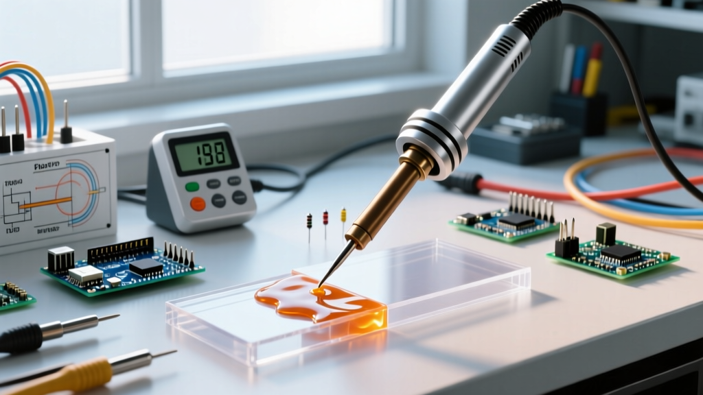
Once the groove is overfilled, increase the iron temperature by 10°C. Wipe the tip on a damp brass sponge to remove any carbonized residue. Gently glide the flat of the spatula or chisel tip over the weld bead to smooth it flush with the surrounding surface. For ABS, you can follow up with an acetone vapor bath to chemically smooth the weld line, rendering it nearly invisible.
Troubleshooting Common Failure Modes
- Brittle, Chalky Welds: Caused by thermal degradation. The iron was too hot, or the tip was held in one spot too long, breaking the polymer chains. Lower the temperature by 15°C and increase your travel speed.
- Delamination (Filler peeling off base): The base plastic was not heated sufficiently to reach its glass transition point. The filler simply sat on top of the cold base. Ensure you are pressing the iron through the filler and into the base groove simultaneously.
- Porosity and Bubbles: Moisture trapped in the filler filament (especially PETG and Nylon) is boiling off. Dry your filler filament in a desiccator or filament dryer at 55°C for 6 hours before using it as a welding rod.
- Black Streaks: Carbonized plastic is stuck to your tip and burning. Clean the tip with brass wool. Never use sandpaper or a steel file on a soldering tip, as this will destroy the iron plating and cause permanent sticking.
Mastering how to plastic weld with a soldering iron bridges the gap between temporary fixes and permanent, structural restorations. By respecting polymer thermal limits, calibrating your station accurately, and utilizing proper joint geometry, you can salvage expensive enclosures, automotive panels, and custom electronics housings with professional-grade results.