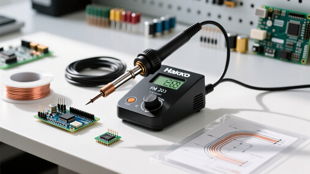

Introduction to the Hakko FM 203 Soldering Station
The Hakko FM 203 soldering station is a premier 3-channel powerhouse designed for high-volume production floors, advanced DIY labs, and aerospace rework environments. In 2026, with the industry's heavy reliance on lead-free SAC305 and SAC405 alloys requiring strict thermal profiles, out-of-the-box factory calibration is rarely sufficient for mission-critical work. Whether you are running micro-soldering with the FM-2024 handpiece or heavy thermal mass desoldering with the FM-2012, precise temperature control is non-negotiable.
This comprehensive tutorial will walk you through the exact hardware setup, digital channel configuration, and thermal calibration procedures required to bring your Hakko FM 203 soldering station into compliance with IPC J-STD-001 and high-reliability NASA NEPP workmanship standards.
Phase 1: Hardware Setup and ESD Grounding
Before powering on the unit, you must establish a verified Electrostatic Discharge (ESD) safe environment. The FM-203 base unit (retailing between $550 and $620 in 2026) features dedicated grounding terminals that must be integrated into your bench's common point ground system.
Step-by-Step Hardware Connection
- Verify Earth Ground: Use a digital multimeter to measure the resistance between your ESD mat's ground snap and the facility's earth ground pin. The reading must be less than 1.0 ohm.
- Connect the Ground Wire: Attach the provided green/yellow grounding wire to the FM-203's rear grounding terminal and secure it to your bench's common point ground bus bar.
- Handpiece Assignment: Connect your handpieces to the front panel DIN connectors. A standard high-efficiency configuration is:
- CH1: FM-2024 (Micro soldering, T36 series tips for 0402 components).
- CH2: FM-2027 (Heavy-duty soldering, T39 series tips for large ground planes).
- CH3: FM-2012 (Desoldering tool for through-hole component extraction).
- Power Initialization: Plug the unit into a surge-protected, grounded 120V/230V outlet (depending on your regional model) and flip the rear rocker switch.
Phase 2: Digital Interface and Channel Configuration
The FM-203 utilizes a digital encoder knob and a high-contrast LCD screen. Proper configuration ensures operators on a production line cannot accidentally alter critical thermal profiles.
Setting Password Protections and Sleep Modes
To prevent unauthorized temperature changes, navigate to the main menu by pressing the central encoder knob. Scroll to System Settings and enable the Key Lock feature. Set a 4-digit PIN. This restricts access to the calibration and temperature offset menus.
Next, configure the Auto-Sleep parameters. For the FM-2024 on CH1, set the sleep timer to 10 minutes to drop the temperature to 150°C, preserving the T36-BZ tip's iron plating. For the FM-2027 on CH2, set the timer to 15 minutes. According to Hakko USA technical bulletins, proper sleep mode utilization extends tip life by up to 40% in active bench environments.
Phase 3: Thermal Calibration Procedure
Factory calibration assumes standard ambient conditions (25°C) and nominal tip aging. To meet IPC Class 3 requirements, you must perform a live thermal offset calibration using a certified tip thermometer.
Expert Note: Never use an infrared (IR) thermal camera to calibrate soldering tips. The varying emissivity of oxidized vs. polished tip surfaces will yield wildly inaccurate readings. Always use a physical K-type thermocouple with thermal interface compound.
Required Calibration Tools
- Hakko 1999 Tip Thermometer (or Fluke 52 II with a K-type surface bead probe).
- Hakko 501-01 Thermal Paste (crucial for accurate heat transfer to the thermocouple).
- Calibration log sheet for ISO 9001 traceability.
Step-by-Step Offset Calibration
- Prepare the Tip: Install a fresh, tinned T39-BC3 tip on the FM-2027 handpiece (CH2). Clean the tip on a brass wire sponge (Hakko 599B).
- Set Target Temperature: Dial the CH2 encoder to 350°C (662°F), the standard baseline for SAC305 lead-free solder.
- Thermal Soak: Allow the station to stabilize for exactly 4 minutes. The FM-203's PID controller needs this time to settle the heater output after the initial overshoot.
- Measure Actual Temperature: Apply a pea-sized drop of Hakko 501-01 thermal paste to the tip's working surface. Press the K-type thermocouple bead firmly into the paste. Wait 15 seconds for the reading to stabilize.
- Calculate the Offset: If the station reads 350°C but the thermocouple reads 342°C, your offset is +8°C.
- Input the Offset: Press the encoder to enter the menu. Navigate to Channel Settings > CH2 > Calibration > Tip Group T39. Use the encoder to dial in the +8°C offset. Press to confirm.
- Verify: Remove the probe, clean the tip, reapply paste, and measure again. The reading should now be 350°C (±2°C tolerance).
Phase 4: Troubleshooting Common FM-203 Error Codes
Even with meticulous setup, high-frequency use can trigger hardware faults. The FM-203's diagnostic system uses specific alphanumeric codes on the LCD. Below is a diagnostic matrix for rapid troubleshooting.
| Error Code | Meaning | Root Cause & Resolution |
|---|---|---|
| S-E | Sensor Error | The thermocouple inside the handpiece is broken or the DIN connection is loose. Check the 5-pin connector for bent pins. Replace the handpiece cord if continuity fails. |
| H-E | Heater Error | The ceramic heating element is open or shorted. Often caused by dropping the FM-2027 handpiece, cracking the internal alumina ceramic. Replace the heating element assembly. |
| C-E | Communication Error | Internal PCB communication fault between the mainboard and the channel sub-boards. Power cycle the unit. If persistent, the mainboard requires factory service. |
| Flashing Temp | Thermal Runaway / Overheat | The PID controller detects the tip exceeding the setpoint by >50°C for more than 5 seconds. Immediately unplug. Check for a shorted TRIAC on the channel's power board. |
Edge Cases: High Thermal Mass PCBs and Ground Planes
A common failure mode when using the Hakko FM 203 soldering station is attempting to solder heavy copper ground planes (e.g., 2oz or 3oz copper on LED MCPCBs) using standard chisel tips. Even with the FM-2027's 72W peak output, a T39-B tip will suffer from thermal stall, dropping below the solder's liquidus temperature and causing cold, grainy joints.
The Solution: Do not simply turn the temperature up to 400°C, which will rapidly oxidize the tip and degrade the flux. Instead, switch to a T39-D52 (massive 5.2mm chisel) or a T39-K (knife blade) tip. These tips possess a larger internal copper core that acts as a thermal capacitor, delivering high instantaneous joule heating to the pad without requiring a higher baseline temperature setting. Maintain your station at 360°C and rely on the tip's thermal mass rather than extreme temperature to overcome the PCB's heat dissipation.
Conclusion and Maintenance Schedule
Setting up and calibrating your Hakko FM 203 soldering station is an investment in yield and reliability. By properly grounding the unit, configuring channel-specific sleep modes, and executing rigorous K-type thermocouple calibrations, you ensure every joint meets stringent 2026 industry standards.
For production environments, log your calibration offsets monthly. If you notice the required offset exceeding ±15°C, it is a definitive indicator that the tip's internal thermocouple is degrading or the ceramic heater's thermal transfer paste has dried out. Proactive replacement of these consumables guarantees the FM-203 will remain the undisputed workhorse of your electronics lab for years to come.