
The Anatomy of a Soldering System Failure
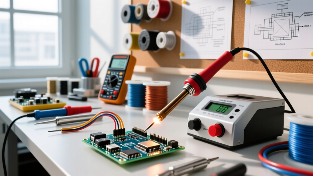
Upgrading from a basic plug-in iron to a professional soldering system—such as the Hakko FX-951, Weller WE1010NA, or JBC CD-2BQF—represents a significant leap in thermal recovery, precision, and ESD safety. However, advanced systems introduce complex failure points: integrated thermocouples, cartridge-based heaters, and micro-processor temperature loops. When your station flashes an error code, fails to melt SAC305 lead-free alloy, or ruins expensive PCB pads through thermal runaway, you need a systematic diagnostic approach.
This comprehensive troubleshooting guide and FAQ addresses the most frequent hardware and metallurgical failures encountered in modern soldering systems, providing exact multimeter readings, metallurgical insights, and actionable fixes aligned with industry workmanship standards.
Rapid Diagnostic Matrix: Soldering System Symptoms
Before dismantling your handpiece, use this matrix to isolate the root cause of your system's malfunction.
| Symptom | Probable Root Cause | Diagnostic Action / Fix |
|---|---|---|
| Station displays "Sensor Error" or "H-E" (Heater Error) | Open circuit in tip heater or thermocouple | Measure tip resistance with a DMM. Replace tip if reading is OL (Open Loop). |
| Tip temperature fluctuates wildly (±30°C) | Failing TRIAC in power supply or oxidized connector pins | Clean handpiece receptacle with contact cleaner; inspect PCB solder joints. |
| Solder balls up and refuses to wet the tip | Severe tip oxidation or iron plating erosion | Use brass wool and tip tinner. Never file or use abrasive sandpaper. |
| Station heats, but thermal recovery is sluggish on ground planes | Wattage limitation or degraded thermal compound in cartridge | Verify wattage (e.g., 65W vs 75W). Upgrade to active-tip cartridge systems like JBC. |
| Mild shock or ESD event on sensitive components | Broken ground wire in handpiece cable | Measure resistance from tip to station ground lug. Must be < 5 ohms. |
Soldering System FAQ: Heating and Thermal Recovery
Why is my Hakko FX-951 flashing a sensor error, and how do I test it?
In composite-tip systems like the Hakko FX-951 (using T18 tips), the ceramic heating element and the temperature sensor are embedded directly inside the tip itself. When the station flashes a sensor or heater error, the internal wire has usually snapped due to mechanical stress or thermal fatigue.
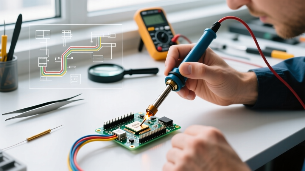
The Multimeter Test: Unplug the station. Set your digital multimeter (DMM) to the lowest Ohms setting (usually 200Ω). Remove the T18 tip and insert the multimeter probes into the two heater pins on the handpiece connector (typically pins 1 and 2 on the aviation-style connector). A healthy T18 heater will read between 2.5Ω and 3.0Ω. If your DMM reads "OL" (Over Limit/Open), the heater is dead. Because the heater is integrated into the tip on Hakko systems, you must replace the entire tip, not the handpiece.
Why does my Weller system struggle with heavy ground planes?
Weller systems (like the WE1010NA) often use traditional thermocouple-based tips where the heater is in the handpiece and the tip is a passive thermal conductor. When soldering heavy copper ground planes, the massive thermal mass pulls heat away faster than a 65W-70W heater can replenish it. If you frequently solder multi-layer PCBs, consider transitioning to an active-cartridge soldering system like the JBC C245 or Pace ADS200. These systems place the heater millimeters from the work surface, utilizing closed-loop algorithms that detect temperature drops in milliseconds and dump up to 130W of instantaneous power into the joint, completely eliminating thermal lag.
Tip Degradation, Oxidation, and Non-Wetting Issues
Why do my tips turn black and stop wetting after just a few weeks?
Black tip syndrome is the bane of modern electronics manufacturing, primarily driven by the industry shift to lead-free solders like SAC305 (Tin/Silver/Copper). SAC305 requires higher operating temperatures (typically 350°C to 380°C) and possesses a high tin content. At elevated temperatures, molten tin aggressively dissolves the iron plating on the tip. Once the microscopic iron layer is breached, the underlying copper core is exposed, oxidizing instantly and creating a non-wettable black crust.
Expert Insight: The Wet Sponge Fallacy
Many technicians still use wet cellulose sponges to clean their tips. Plunging a 380°C tip into room-temperature water causes rapid thermal contraction. Over time, this thermal shock creates micro-fractures in the iron plating, allowing solder to seep underneath and destroy the tip from the inside out. Always use dry brass wire wool or specialized tip-cleaning paste to preserve the iron layer.
According to the IPC J-STD-001 standard for soldered electrical assemblies, proper wetting is critical for reliable metallurgical bonds. To maintain wetting, always leave a generous blob of solder on the tip before powering down the system. This "sacrificial layer" oxidizes instead of the iron plating while the station is off.
Can I salvage a completely oxidized tip?
If the tip is merely coated in burnt flux and light oxidation, a chemical tip tinner (a mixture of aggressive flux and solder powder) can strip the oxides and re-tin the surface in seconds. However, if the tip exhibits physical pitting, craters, or visible copper discoloration, the iron plating is permanently destroyed. No amount of chemical flux will restore it; attempting to file or sand the tip will only expose more copper, rendering it useless. Replace the cartridge immediately.
ESD Grounding and Safety Troubleshooting
How do I verify that my soldering system is properly grounded?
Electrostatic Discharge (ESD) can instantly destroy sensitive MOSFETs and microcontrollers. A professional soldering system features a dedicated grounding path that runs from the soldering tip, through the handpiece cable, into the station's chassis, and out to an ESD mat or wrist strap. According to the ESD Association fundamentals, this path must be continuous but current-limiting to protect the operator from accidental mains voltage shocks.
The Verification Procedure:
- Set your DMM to measure resistance (Ohms).
- Place one probe on the metal shaft of the soldering tip (ensure it touches bare metal, not the plated working end).
- Place the second probe on the station's dedicated ground binding post or the ground pin of the AC power plug.
- The reading should be less than 5 ohms. If the reading is open (OL) or highly erratic, the internal ground wire in your handpiece cable has fractured, usually near the strain relief. The cable or handpiece must be replaced.
For high-reliability aerospace or medical applications, technicians must adhere to strict workmanship protocols. The NASA Workmanship Training and Certification Program mandates regular verification of soldering equipment grounding to ensure zero potential difference between the operator, the PCB, and the soldering iron.
Handpiece Cable and Connector Failures
My station works intermittently when I move the cable. What is failing?
Intermittent heating or sudden station reboots when moving the handpiece almost always point to a cable failure. The flexible silicone cables used in systems like the Hakko FM-206 or Weller WX series endure extreme mechanical stress. The most common failure points are:
- The Strain Relief Boot: The rubber boot where the cable enters the handpiece often hides fractured copper strands. Bend the cable sharply at this point while the station is on; if the heater clicks off, the cable is internally broken.
- Connector Pins: The DIN or aviation connectors at the base station can suffer from pin retraction or oxidation. Inspect the male pins on the handpiece plug. If they are darkened, clean them gently with isopropyl alcohol and a fiberglass scratch pen. If a pin is pushed back into the plastic housing, use a needle-nose plier to carefully pull it forward and re-seat the internal retaining clip.
Preventative Maintenance Schedule for Soldering Systems
To maximize the lifespan of your equipment and ensure compliance with IPC workmanship standards, implement the following maintenance matrix in your lab or workshop:
- Daily: Inspect the tip for pitting or black oxidation. Re-tin the tip with fresh, flux-cored solder before powering off the station. Empty the brass wool shavings tray to prevent conductive debris from shorting out the station base.
- Weekly: Wipe down the handpiece cable with isopropyl alcohol to remove acidic flux residues that degrade silicone over time. Inspect the connector pins for discoloration.
- Monthly: Calibrate the station's temperature output using a digital tip thermometer (e.g., Hakko FG-100B). Verify that the displayed temperature matches the actual tip temperature within ±5°C. Test the ESD ground path resistance with a multimeter.
- Annually: Replace the handpiece cable assembly proactively if used in a high-volume production environment, as internal wire fatigue is inevitable regardless of careful handling.
Final Thoughts on System Diagnostics
Troubleshooting a soldering system requires understanding both the electrical architecture of the station and the metallurgy of the solder joint. By utilizing a multimeter to verify heater resistance, abandoning thermal-shock-inducing wet sponges, and rigorously maintaining your ESD ground path, you can eliminate 95% of common station failures. Investing time in these diagnostic routines ensures your equipment consistently produces the flawless, shiny, concave fillets demanded by modern electronics manufacturing standards.