
The Core Challenge: Thermal Sensitivity in SMD LEDs
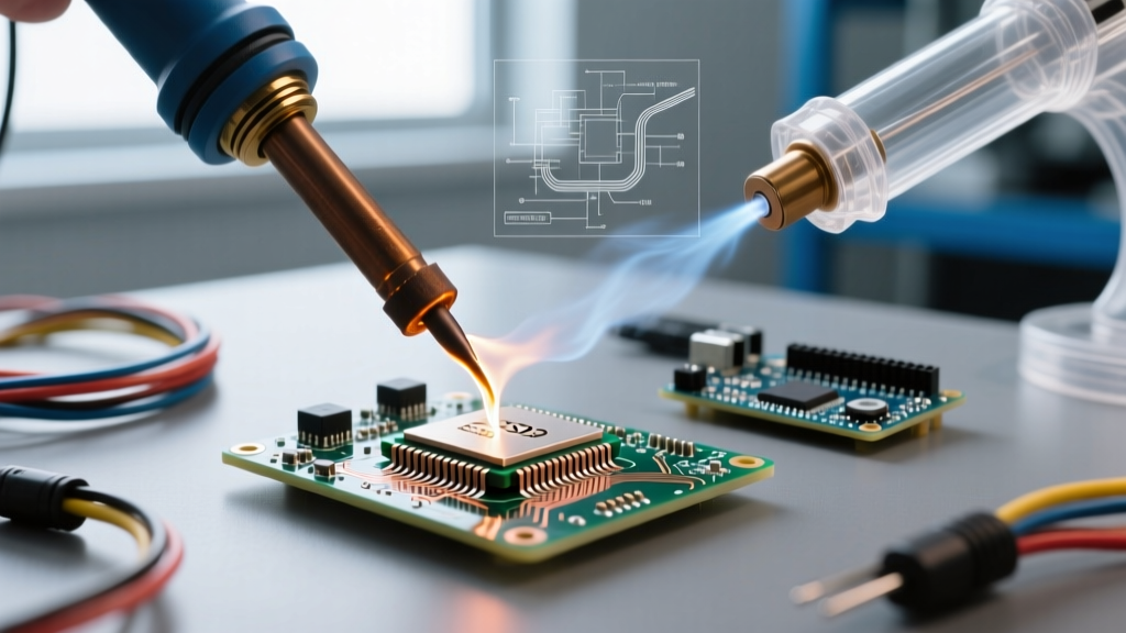
Soldering Surface-Mount Device (SMD) LEDs presents a unique metallurgical and thermal puzzle. Unlike passive resistors or ceramic capacitors, SMD LEDs are encapsulated in epoxy or silicone resins that degrade rapidly when exposed to prolonged heat. Furthermore, the internal gold or copper wire bonds connecting the semiconductor die to the anode and cathode pads are highly susceptible to thermal shock. Exceeding a dwell time of 3 seconds at temperatures above 260°C can cause internal delamination, resulting in a dead or flickering LED.
According to the IPC J-STD-001 standard for soldered electrical assemblies, thermal profiling is critical when working with heat-sensitive components. To achieve reliable joints without destroying the component, makers and engineers must select the correct methodology based on production volume, pad geometry, and available budget. This decision framework will guide you through the exact tools, materials, and techniques required for SMD LED soldering in 2026.
Decision Matrix: Choosing Your SMD LED Soldering Method
Select the optimal path based on your project scope. Use the matrix below to align your methodology with your specific constraints.
| Method | Ideal Volume | Setup Cost (2026) | Skill Curve | Thermal Risk to LED |
|---|---|---|---|---|
| Precision Hand Soldering | 1–10 boards (Prototyping) | $120 – $350 | High | Moderate (Operator dependent) |
| Hot Air Rework | 10–50 boards (Mid-Volume) | $250 – $500 | Moderate | Low (If profiled correctly) |
| DIY Reflow Hotplate | 50+ boards (Batch Production) | $80 – $200 | Low (Once profiled) | Very Low (Controlled ramp) |
Path A: Precision Hand Soldering (For Prototypes & Repairs)
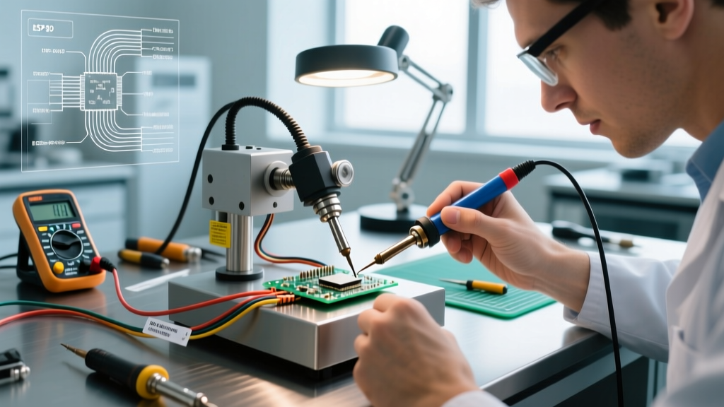
When modifying a single PCB or repairing a damaged indicator LED, hand soldering is unavoidable. The secret to hand soldering SMD LEDs lies in minimizing thermal mass transfer time while ensuring adequate wetting.
Tool & Tip Selection
Do not use standard chisel tips. For 0603, 0805, and 1206 SMD LEDs, you need a micro-pencil or ultra-fine conical tip. The Hakko T18-IL or the Weller RT3 (for the WT1012 station) are industry benchmarks. These tips concentrate heat into a sub-millimeter point, allowing you to touch the pad and the LED terminal simultaneously without melting the adjacent epoxy lens.
- Temperature Setting: Set your station to 315°C (600°F). While this seems high, the micro-tip loses heat instantly upon contact with the copper pad. A higher baseline ensures rapid thermal recovery, keeping your dwell time under 1.5 seconds per joint.
- Solder Wire: Use a thin diameter wire, specifically 0.015" (0.38mm). Kester 44 or Alpha Metals Sn63/Pb37 with a rosin core provides the necessary flux activity for rapid wetting.
The "Tack and Drag" Technique
- Apply a microscopic amount of tack flux (e.g., Amtech NC-559-V2-TF) to the PCB pads.
- Tin only one pad with a tiny bead of solder.
- Using fine-point tweezers (like the Hakko CHP-TW1Z), place the SMD LED onto the pads. Note the polarity indicator (usually a green dot or a beveled corner on the LED casing).
- Melt the tinned pad and slide the LED into the molten solder. Remove the iron and hold the LED still for 2 seconds until the joint solidifies.
- Solder the opposite pad. The entire process should take less than 4 seconds.
Path B: Hot Air Rework (For Dense Arrays & Mid-Volume)
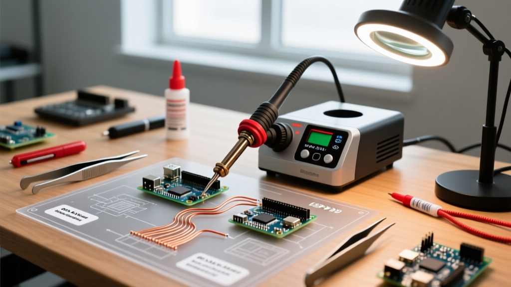
If you are populating a custom LED matrix or a board with 50+ SMD LEDs, hand soldering introduces too much variability and fatigue. Hot air rework, combined with solder paste, is the superior choice.
Equipment Configuration
The Quick 861DW remains the gold standard for hot air stations in 2026, offering programmable temperature profiles and precise airflow control. When blowing hot air on lightweight 0805 LEDs, excessive airflow will literally blow the components off the pads before the solder melts.
Expert Configuration for 0805/1206 LEDs:Temperature: 350°C (662°F)
Airflow: 20% to 30% (approx. 15-20 L/min)
Nozzle: 4mm round nozzle to focus heat strictly on the component footprint.
The Stencil and Paste Workflow
For arrays, apply solder paste using a laser-cut stainless steel stencil. Use a leaded paste like Chip Quik SMD430AX5 (Sn63/Pb37). The lower melting point of leaded solder (183°C) compared to lead-free SAC305 (217°C) provides a massive safety margin for the LED's epoxy housing. After placing the LEDs with a vacuum pickup pen, apply hot air in a slow, circular motion, keeping the nozzle 10mm above the board. The paste will transition from a dull grey to a shiny, reflective liquid the moment it reaches its liquidus state.
Path C: Controlled DIY Reflow (For Production Batches)
When producing hundreds of LED driver boards, manual placement and hot air become bottlenecks. Desktop reflow hotplates have revolutionized small-batch manufacturing. Devices like the Miniware MHP50 or the Pine64 Pinecil paired with a custom hotplate jig offer closed-loop PID temperature control.
According to SparkFun's comprehensive SMD manufacturing guidelines, following a proper reflow profile (Preheat, Soak, Reflow, Cooling) is essential to prevent "tombstoning"—a defect where the LED stands on one end due to uneven surface tension. A controlled hotplate ramps the entire board evenly, ensuring both the anode and cathode pads reach the liquidus temperature simultaneously, pulling the LED flat against the PCB via surface tension.
Material Science: Flux and Alloy Specifics
The choice of solder alloy directly impacts the longevity of your SMD LEDs.
- Sn63/Pb37 (Leaded): Melts at 183°C. Highly recommended for DIY and mid-volume LED work. The lower thermal requirement drastically reduces the risk of scorching the LED diffuser lens or degrading the phosphor layer in white LEDs.
- SAC305 (Lead-Free): Melts at 217°C. Required for commercial, RoHS-compliant products. If you must use SAC305, ensure your LEDs are rated for lead-free reflow profiles (capable of withstanding 260°C for 10 seconds).
- Flux Chemistry: Always use a No-Clean (NC) or Water-Soluble (WS) flux specifically formulated for SMD pastes. Avoid highly acidic plumbing fluxes, which will corrode the delicate silver terminations on the LED pads.
Troubleshooting Edge Cases in SMD LED Soldering
Even with the right framework, physical anomalies occur. Reference this troubleshooting matrix to diagnose failures based on the NASA Workmanship Standard for soldering.
1. The "Popcorn" Effect (Cracked LED Lenses)
Cause: Moisture trapped inside the LED's epoxy or silicone body turns to steam during reflow, cracking the casing from the inside out.
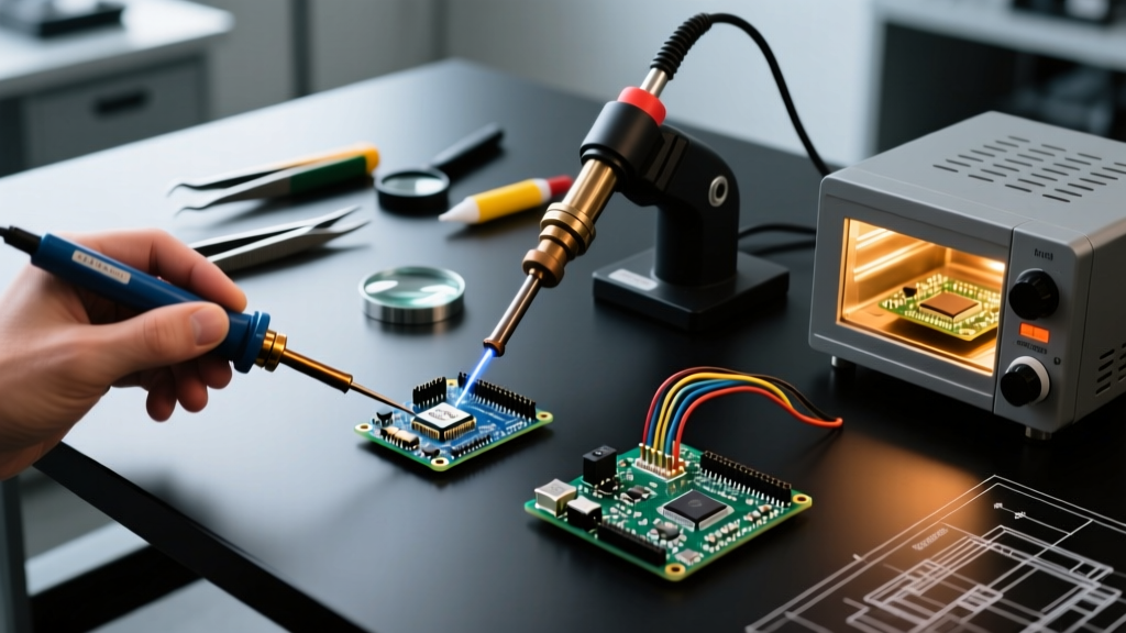
Solution: SMD LEDs are highly moisture-sensitive (usually MSL 3 or 4). You must bake your LED reels in a component dry box or a convection oven at 60°C for 24 hours prior to soldering to drive out absorbed ambient humidity.
2. Tombstoning (Billboarding)
Cause: One pad heats faster than the other, causing the molten solder's surface tension to pull the LED upright.
Solution: Ensure your PCB footprint design includes thermal relief on ground planes. If a cathode pad is connected directly to a massive copper pour, it will act as a heatsink, delaying the melting of the paste on that side. Use spoke-thermal vias in your CAD design.
3. LED Discoloration / Yellowing
Cause: Prolonged exposure to rosin-based flux fumes or excessive tip temperatures during hand soldering.
Solution: Lower your iron dwell time. If using hot air, ensure you are not lingering on the component after the solder has flashed to a liquid state. Clean the board with 99% Isopropyl Alcohol and a soft ESD-safe brush immediately after cooling.
Final Expert Checklist
"The success of SMD LED soldering is determined 80% before the iron even touches the board. Proper footprint design, moisture baking, and precise paste deposition are the true metrics of a reliable assembly."
- [ ] Verify LED polarity markings against the PCB silkscreen.
- [ ] Bake moisture-sensitive LEDs if the factory seal has been open for >48 hours.
- [ ] Select Sn63/Pb37 for maximum thermal safety margin on non-RoHS prototypes.
- [ ] Use micro-pencil tips and 0.015" wire for hand soldering to limit dwell time to <2 seconds.
- [ ] Inspect joints under a 10x loupe to ensure proper fillet formation and no solder bridging.
By applying this decision framework, you eliminate the guesswork from SMD LED assembly. Whether you are repairing a single 5050 RGB LED on a gaming controller or reflowing a 100-LED matrix for an architectural lighting project, matching your methodology to your volume and thermal constraints guarantees professional, luminous results.