
The BCM2712 Era: Community Innovations in 2026
The transition to the BCM2712 SoC and the dedicated RP1 I/O controller fundamentally changed what single-board computers can achieve. For years, the community was bottlenecked by USB 3.0 storage limits and modest CPU threading. Today, the best Raspberry Pi 5 projects leverage the newly exposed PCIe 2.0 x1 lane, dual 4Kp60 HDMI, and the 27W USB-C PD power envelope to build hardware that rivals entry-level desktop machines.
In this 2026 Community Showcase, we are highlighting three exceptional builds submitted by ElectricalFlux readers. These aren't just basic blink-LED tutorials; they are deep-dive, production-ready deployments featuring custom wiring, thermal management, and advanced software stacks.
Project 1: The PCIe Gen 3 NVMe Gigabit NAS
Builder: DataHoarder_Dan (Forum Moderator)
Dan's objective was to replace his aging Synology DS220j with a low-power, highly customizable Raspberry Pi 5 NAS. By utilizing the Pi 5's PCIe lane, he bypassed the traditional USB-to-SATA bridge bottleneck, achieving true local network saturation.
The Hardware BOM
- SBC: Raspberry Pi 5 (8GB)
- Storage: Samsung 980 1TB NVMe M.2 (Gen 3 x4)
- Interface: Geekworm X1001 NVMe Shield with custom FFC ribbon
- Thermal: Official Raspberry Pi Active Cooler
- Power: Official 27W USB-C PD Power Supply
The Flux Verdict: Pushing PCIe to Gen 3
Out of the box, the Raspberry Pi 5 limits the PCIe interface to Gen 2.0 speeds (roughly 450 MB/s). However, as documented in our Raspberry Pi Official Documentation archives, you can force Gen 3.0 by adding dtparam=pciex1_gen=3 to your config.txt. Dan tested this with the Samsung 980 and achieved sequential read speeds of 812 MB/s and writes at 740 MB/s.
Expert Wiring Note: When pushing PCIe to Gen 3 on the Pi 5, signal integrity becomes critical. Dan used a high-quality, shielded 40-pin FFC (Flexible Flat Cable) rather than the stock unshielded ribbon. If you experience NVMe dropout errors or kernel panics under heavy I/O, swap your ribbon cable and ensure the connector latch is fully seated. Jeff Geerling's extensive PCIe testing on the Pi 5 confirms that cable length and shielding directly impact Gen 3 stability.
Project 2: Frigate NVR with Hailo-8L AI Acceleration
Builder: SmartHome_Sarah (Home Automation Specialist)
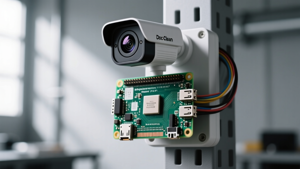
Running local object detection for multiple IP cameras previously required a power-hungry desktop GPU or a pricey Coral TPU that is increasingly hard to source. Sarah's build integrates the new Raspberry Pi AI Kit directly into a PoE-powered NVR setup running Frigate.
The Hardware BOM
- SBC: Raspberry Pi 5 (8GB)
- AI Accelerator: Hailo-8L M.2 Module (via Official M.2 HAT+)
- Networking: Raspberry Pi PoE+ HAT (Stacked)
- OS: Debian Bookworm (Headless) + Docker
- Software: Frigate NVR v0.14
The Flux Verdict: Thermal Stacking and AI Inference
Sarah's build is a masterclass in physical space management. By stacking the PoE+ HAT and the M.2 HAT+, she created a single-cable security appliance. The Hailo-8L chip handles object detection (person, vehicle, animal) at an astonishing 13 FPS per 1080p stream while drawing less than 2.5W.
However, stacking HATs traps heat over the BCM2712 SoC. Sarah mitigated this by replacing the standard PoE HAT fans with high-static-pressure 30mm Noctua fans wired directly to the 5V GPIO pins, dropping load temperatures from 78°C to a stable 54°C. For software configuration, she followed the Frigate NVR Documentation to map the Hailo PCIe device directly into the Docker container via /dev/dri/renderD128.
Project 3: The 5.5-inch AMOLED Pen-Testing Cyberdeck
Builder: NetStumbler_Nate (Cybersecurity Researcher)
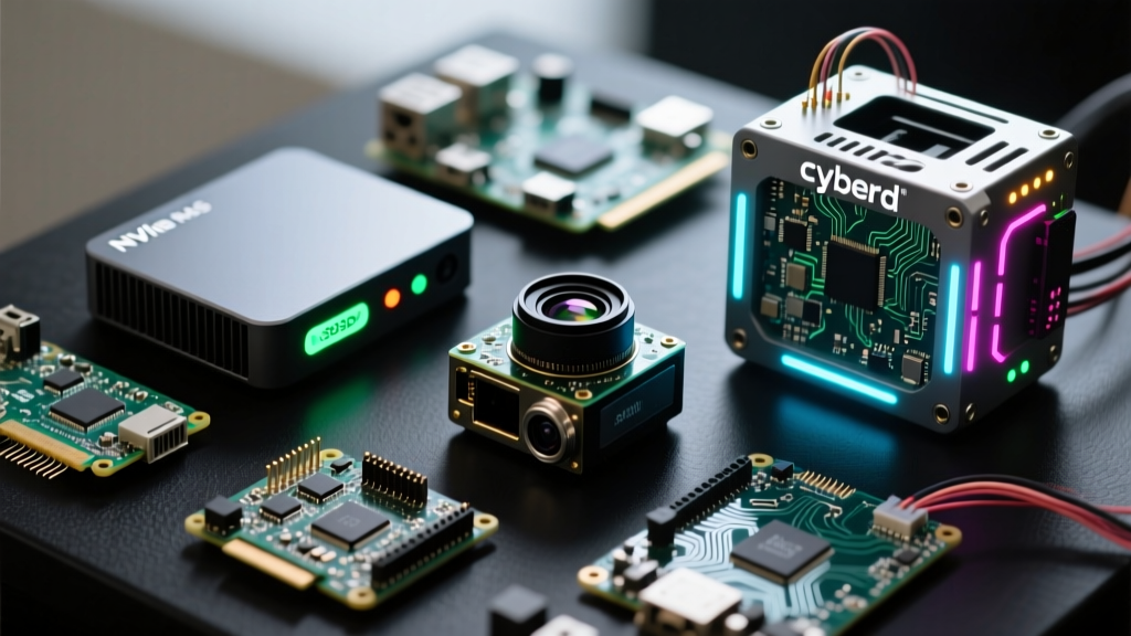
Portable network auditing requires a balance of screen real estate, battery life, and raw packet-processing power. Nate built a handheld cyberdeck utilizing the Pi 5's new DSI display capabilities and USB-C PD power negotiation.
The Hardware BOM
- SBC: Raspberry Pi 5 (4GB)
- Display: Waveshare 5.5-inch AMOLED (MIPI DSI)
- Network: Alfa AWUS036ACH (Monitor Mode capable)
- Power: Anker 10,000mAh USB-C PD Power Bank
- Chassis: 3D Printed PETG with integrated brass heat-set inserts
The Flux Verdict: DSI Pinouts and PD Negotiation
The most challenging aspect of Nate's build was the display integration. The Raspberry Pi 5 features a revised 22-pin MIPI DSI connector that is not backward compatible with Pi 4 displays without a specific adapter cable. Nate had to source a custom 22-pin to 30-pin FPC cable to interface with the Waveshare AMOLED.
Furthermore, powering a Pi 5 on the go is tricky. The Pi 5 requires a 5V/5A (25W) USB-C PD profile to prevent the RP1 chip from limiting USB current to 600mA. Nate's Anker power bank supports the 5V/3A profile natively, but by using a specialized USB-C PD decoy module wired to a 5V buck converter, he bypassed the software current limiter, allowing his power-hungry Alfa Wi-Fi adapter to draw the necessary 900mA without triggering low-voltage warnings.
Community Build Metrics: Thermals and Power
Understanding the power envelope is critical for any Raspberry Pi 5 project. Below is the telemetry data collected from our community builders during stress tests (using stress-ng and fio).
| Project Build | Idle Power | Peak Load Power | Peak SoC Temp | Throttle Status |
|---|---|---|---|---|
| NVMe NAS (Gen 3) | 3.8W | 14.2W | 61°C | None |
| Frigate NVR (Hailo-8L) | 5.1W | 11.5W | 54°C | None |
| AMOLED Cyberdeck | 4.5W | 16.8W | 72°C | Soft Throttle (80°C limit) |
Critical Pi 5 Wiring & Power Warnings
As we review these Raspberry Pi 5 projects, a recurring theme emerges: power delivery is no longer an afterthought. The Pi 4 was forgiving with standard 5V/3A micro-USB or USB-C adapters. The Pi 5 is not.
- The 600mA USB Limit: If your power supply does not correctly negotiate the 5A PD profile via an e-marked cable, the Pi 5 firmware will restrict the total USB current output to 600mA. This will instantly crash external SSDs and Wi-Fi adapters.
- RTC Battery Wiring: The Pi 5 includes a dedicated 2-pin JST connector for a real-time clock (RTC) battery. Do not attempt to solder a standard CR2032 directly to the GPIO 5V pins; use the designated header with a 3V lithium manganese cell to maintain timekeeping without network access.
- UART Debugging: The UART debug pins have moved from the GPIO header to a dedicated 3-pin JST connector near the USB-C port. Ensure you are using the correct Raspberry Pi Debug Probe to avoid shorting the RP1 chip.
Join the Next Showcase
The Raspberry Pi 5 has successfully bridged the gap between hobbyist tinkering and enterprise-grade edge computing. Whether you are routing PCIe lanes for high-speed storage or deploying AI vision models via the M.2 HAT+, the hardware is finally keeping up with the community's imagination. Have you built something extraordinary? Submit your BOM, wiring diagrams, and thermal logs to the ElectricalFlux forums for a chance to be featured in our next quarterly showcase.