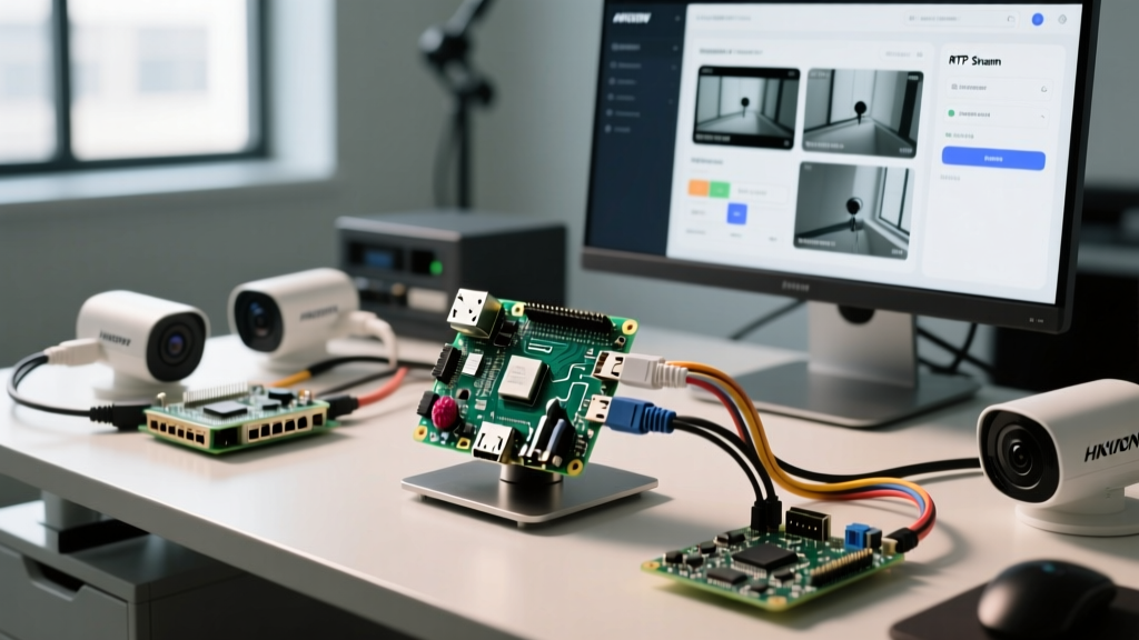
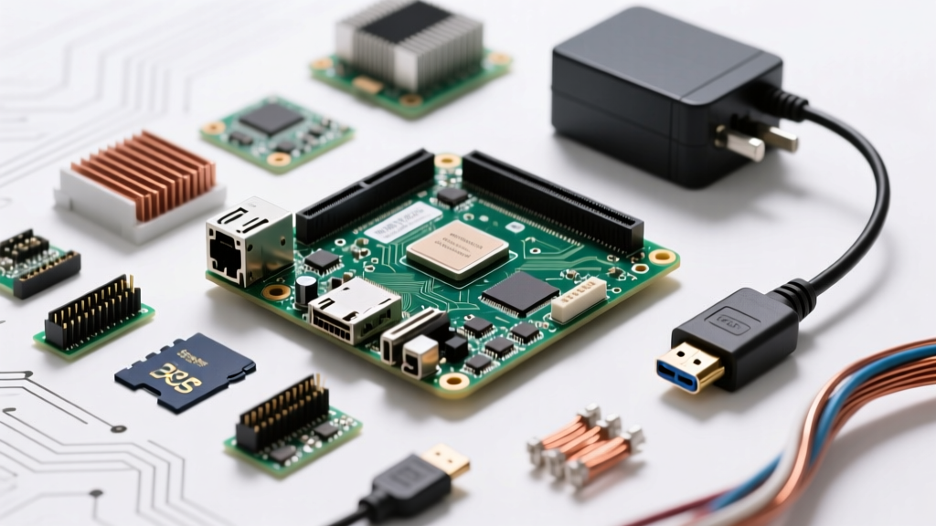
The GPIO pins on Raspberry Pi 5 represent a major architectural shift from previous generations. Because the Pi 5 offloads peripheral control to the new RP1 southbridge chip, legacy libraries like RPi.GPIO are largely deprecated, and the default logic level behavior for pull-up/pull-down resistors has changed. If you are wiring sensors or relays in 2026, you must use the lgpio backend (via gpiozero) and account for the Pi 5's strict 3.3V logic thresholds.
This guide cuts through the outdated tutorials. We will walk through a concrete decision framework for board selection, map out a PIR-triggered relay build, provide production-ready Python code, and debug the exact RP1-specific errors you will encounter on the bench.
The 2026 Decision Tree: Which Board for GPIO Projects?
Before stripping wire, you need to match your project's I/O demands to the right silicon. The Pi 5 is not always the correct tool for a simple GPIO toggle.
| Criteria | Raspberry Pi 5 (8GB) | Raspberry Pi 4 Model B (4GB) | Raspberry Pi Zero 2 W |
|---|---|---|---|
| GPIO Count | 26 usable (40-pin header) | 26 usable (40-pin header) | 26 usable (40-pin header) |
| I2C/SPI Buses | Multiple (via RP1 routing) | 2x I2C, 2x SPI (standard) | 1x I2C, 1x SPI (limited) |
| 5V Pin Current Capacity | Up to 5A (via USB-C PD) | ~1.2A typical limit | Highly restricted (~0.5A) |
| GPIO Library Backend | lgpio (Mandatory) |
RPI.GPIO or lgpio |
RPI.GPIO or lgpio |
| Best Application | Multi-bus, high-power 5V rail, CV | Standard home automation | Headless, single-sensor nodes |
Hardware Spec Sheet: Parts List and Pin Mapping
For this build, we are creating a PIR-triggered security relay. The HC-SR501 PIR sensor outputs 3.3V when triggered (perfect for Pi logic), and we are using a 3.3V-specific relay to avoid back-EMF frying the RP1 chip.
Exact Parts List
- Compute: Raspberry Pi 5 (8GB variant, SKU: SC1142) running Raspberry Pi OS Bookworm.
- Sensor: HC-SR501 PIR Motion Sensor (adjusted to 3.3V output via onboard jumper or logic level).
- Actuator: Songle SRD-03VDC-SL-C (3.3V DC coil) Relay Module with optocoupler isolation.
- Wiring: 24 AWG solid core jumper wires (Dupont connectors).
Pin Mapping Table
Always use BCM (Broadcom) numbering in your code, not physical pin numbers. Reference pinout.xyz for visual confirmation.
| Component | Physical Pin | BCM GPIO | Wire Color | Function |
|---|---|---|---|---|
| PIR VCC | Pin 2 | 5V Power | Red | Sensor power (requires 5V for HC-SR501 internal regulator) |
| PIR OUT | Pin 11 | GPIO 17 | Yellow | Digital HIGH (3.3V) on motion detect |
| Relay VCC | Pin 1 | 3.3V Power | Orange | Relay coil power (Must be 3.3V for this specific module) |
| Relay IN | Pin 13 | GPIO 27 | Green | Trigger signal (Active LOW) |
| Common GND | Pin 6 | Ground | Black | Shared ground for Pi, PIR, and Relay |
Step-by-Step Build: PIR-Triggered Security Relay
- Prep the OS: Flash Raspberry Pi OS Bookworm (64-bit). Boot, open terminal, and run
sudo raspi-config. Navigate to Interface Options > I2C and enable it (good practice to enable standard buses). Reboot. - Install Dependencies: The Pi 5 requires the
lgpioC library for Python GPIO access. Run:sudo apt update && sudo apt install python3-gpiozero python3-lgpio - Wire the DC Side: Connect the PIR VCC to Pin 2 (5V). Connect the PIR OUT to Pin 11 (GPIO 17). Connect the Relay VCC to Pin 1 (3.3V) and Relay IN to Pin 13 (GPIO 27). Tie all GNDs to Pin 6.
- Calibrate the PIR: Use a small Phillips screwdriver to adjust the "Time Delay" potentiometer on the HC-SR501 fully counter-clockwise (minimum ~3 seconds) for testing. Leave the "Trigger" jumper on single-trigger mode (H).
- Verify Logic Levels: Before connecting AC, use your multimeter to probe the Relay IN pin while running the test script. You should see it drop from 3.3V to near 0V when motion is detected (active LOW).
Complete Python Control Code (Target: Raspberry Pi 5)
This script targets the Raspberry Pi 5 (8GB) using the gpiozero library, which automatically routes through the lgpio backend on Bookworm. It includes explicit pin definitions, state tracking, and a finally block to ensure the relay disengages if the script crashes.
#!/usr/bin/env python3
"""
PIR-Triggered Security Relay for Raspberry Pi 5
Requires: python3-gpiozero, python3-lgpio
"""

from gpiozero import MotionSensor, OutputDevice
from signal import pause
import time
import sys

# --- PIN DEFINITIONS (BCM Numbering) ---
PIR_PIN = 17      # Physical Pin 11
RELAY_PIN = 27    # Physical Pin 13

# --- HARDWARE CONFIGURATION ---
# HC-SR501 outputs HIGH (3.3V) on motion
pir = MotionSensor(PIR_PIN, queue_len=1, pull_up=False)

# Relay module is Active LOW (trigger on 0V)
# active_high=False tells gpiozero to invert the logic safely
relay = OutputDevice(RELAY_PIN, active_high=False, initial_value=False)

def system_startup():
    print(f"[INIT] GPIO Pins on Raspberry Pi initialized.")
    print(f"[INIT] Monitoring PIR on BCM {PIR_PIN}, controlling Relay on BCM {RELAY_PIN}.")
    # Ensure relay is OFF on startup
    relay.off()

def on_motion_detected():
    print(f"[{time.strftime('%H:%M:%S')}] MOTION DETECTED: Engaging relay.")
    relay.on()

def on_motion_stopped():
    print(f"[{time.strftime('%H:%M:%S')}] MOTION CLEARED: Disengaging relay.")
    relay.off()

if __name__ == "__main__":
    try:
        system_startup()
        # Bind events
        pir.when_motion = on_motion_detected
        pir.when_no_motion = on_motion_stopped

        print("[RUN] System active. Press Ctrl+C to exit.")
        pause() # Keeps script running efficiently

    except KeyboardInterrupt:
        print("\n[EXIT] Manual interrupt received.")
    except Exception as e:
        print(f"[FATAL] Unexpected error: {e}", file=sys.stderr)
    finally:
        # CRITICAL: Hardware cleanup to prevent relay sticking on crash
        print("[CLEANUP] Forcing relay OFF and releasing GPIO pins.")
        relay.off()
        relay.close()
        pir.close()
Debugging GPIO Failures: Exact Errors and Ranked Fixes
When working with the RP1 chip on the Pi 5, you will encounter specific errors that older forums cannot solve. Here are the exact error strings and how to fix them.
Error 1: RuntimeError: Cannot determine SOC peripheral base address
The Cause: You are trying to use the legacy RPi.GPIO library on a Raspberry Pi 5. The Pi 5's memory map is entirely different, and RPi.GPIO cannot find the old BCM2835/2711 peripheral addresses.
The Fix:
1. Uninstall the legacy library: pip3 uninstall RPi.GPIO
2. Ensure lgpio is installed: sudo apt install python3-lgpio
3. Use gpiozero (as shown in the code above), which automatically uses lgpio as its backend on the Pi 5.
Error 2: OSError: [Errno 121] Remote I/O error (If adding I2C sensors later)
The Cause: The Pi 5's RP1 chip handles I2C pull-up resistors differently. If your sensor module lacks physical 4.7kΩ pull-up resistors on the SDA/SCL lines, the bus will float and throw this error.
The Fix: Solder 4.7kΩ pull-up resistors between the 3.3V line and both SDA and SCL on your sensor breakout board. Do not rely on the Pi 5's internal software pull-ups for I2C.
The First 3 Things to Check When GPIO Fails
- Numbering Scheme Mismatch: Did you wire to Physical Pin 13 but define
RELAY_PIN = 13in code? Physical Pin 13 is BCM GPIO 27. Always map physical to BCM usingpinout.xyz. - Backend Verification: Run
python3 -c "import gpiozero; print(gpiozero.Device._default_pin_factory)". It should outputlgpio. If it outputsrpigpio, your environment is misconfigured for Pi 5. - Voltage Starvation: Measure the 3.3V rail (Pin 1) under load with a multimeter. If it drops below 3.1V when the relay triggers, your power supply is browning out the Pi. Use an official 27W USB-C PD power supply.
Extending and Simplifying the Build
To Simplify: If you don't need to switch AC mains and just want a visual indicator, strip out the relay module entirely. Replace the OutputDevice with a LED object from gpiozero, wire a standard 5mm LED with a 220Ω current-limiting resistor to GPIO 27, and reduce the hardware footprint to a single breadboard.
To Extend: To make this a true IoT node, integrate the paho-mqtt library. Add an MQTT publish call inside the on_motion_detected function to send a JSON payload {"event": "motion", "state": 1, "ts": time.time()} to a local Mosquitto broker. This allows Home Assistant to ingest the Pi 5's GPIO state natively over your network without polling, turning a standalone bench project into a permanent smart-home fixture.