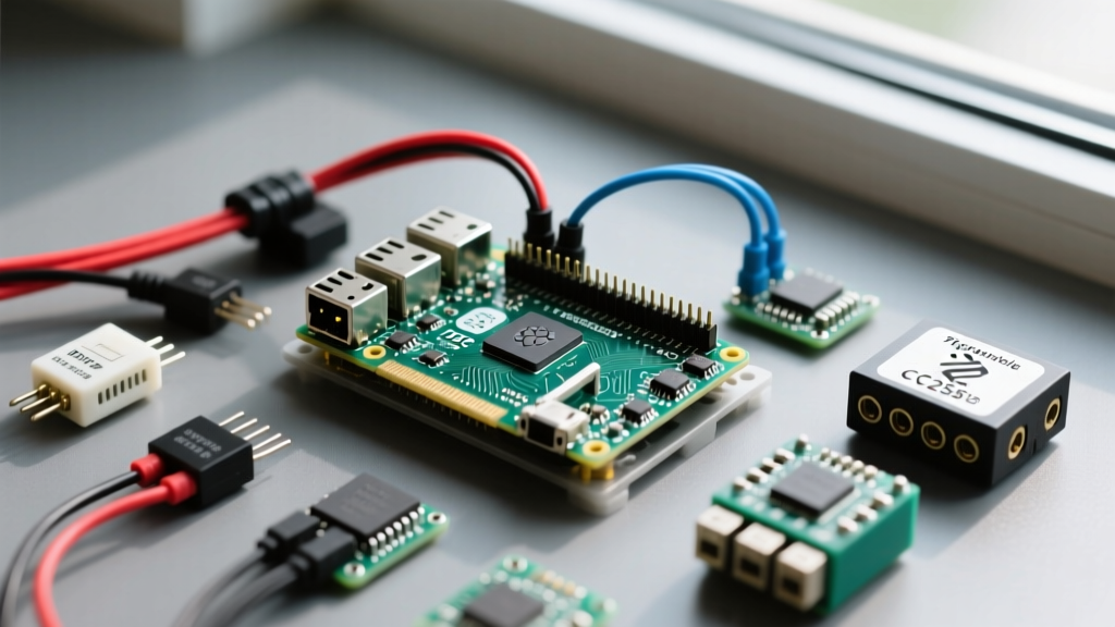
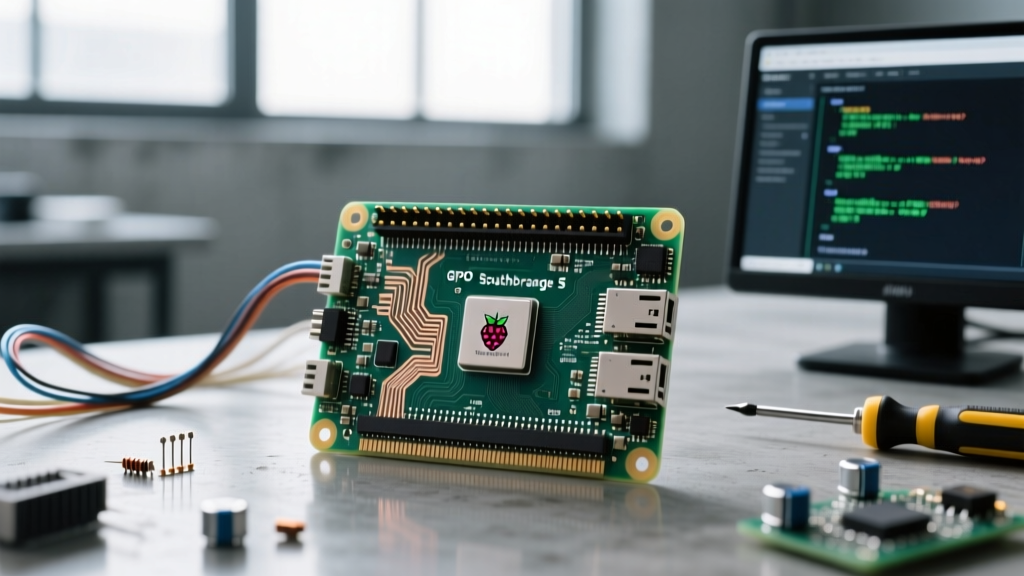
The Raspberry Pi 5 retains the physical 40-pin header layout of its predecessors, but the underlying architecture has fundamentally changed. GPIO is now managed by the RP1 southbridge chip, which alters drive strengths (up to 12mA default), default pull-up states, and peripheral routing. If you are migrating from a Pi 4, assuming the electrical characteristics are identical will lead to logic errors or damaged silicon.
The Complete Raspberry Pi 5 GPIO Pinout Reference
The table below maps the physical header pins to the RP1/BCM GPIO numbers and their primary alternate functions. Read this table assuming the board is oriented with the USB ports facing you and the GPIO header on the top right.
| Pin | BCM/GPIO | Name | Function / RP1 Notes |
|---|---|---|---|
| 1 | - | 3V3 | 3.3V Power (Max 1.5A total across all 3V3 pins) |
| 2 | - | 5V | 5V Power (Direct from USB-C/PMIC) |
| 3 | 2 | SDA1 | I2C1 Data (Hardware 1.8k pull-up to 3.3V) |
| 4 | - | 5V | 5V Power |
| 5 | 3 | SCL1 | I2C1 Clock (Hardware 1.8k pull-up to 3.3V) |
| 6 | - | GND | Ground |
| 7 | 4 | GPCLK0 | General Purpose Clock 0 |
| 8 | 14 | TXD0 | UART0 Transmit (Primary console/serial) |
| 9 | - | GND | Ground |
| 10 | 15 | RXD0 | UART0 Receive |
| 11 | 17 | GPIO17 | General Purpose / SPI1 CE1 |
| 12 | 18 | PWM0 | Hardware PWM0 / SPI1 CE0 |
| 13 | 27 | GPIO27 | General Purpose |
| 14 | - | GND | Ground |
| 15 | 22 | GPIO22 | General Purpose |
| 16 | 23 | GPIO23 | General Purpose / SPI1 CE2 |
| 17 | - | 3V3 | 3.3V Power |
| 18 | 24 | GPIO24 | General Purpose |
| 19 | 10 | MOSI | SPI0 MOSI (Main SPI Data Out) |
| 20 | - | GND | Ground |
| 21 | 9 | MISO | SPI0 MISO (Main SPI Data In) |
| 22 | 25 | GPIO25 | General Purpose |
| 23 | 11 | SCLK | SPI0 Clock |
| 24 | 8 | CE0 | SPI0 Chip Select 0 |
| 25 | - | GND | Ground |
| 26 | 7 | CE1 | SPI0 Chip Select 1 |
| 27 | 0 | ID_SD | I2C0 Data (HAT EEPROM ID only) |
| 28 | 1 | ID_SC | I2C0 Clock (HAT EEPROM ID only) |
| 29 | 5 | GPIO5 | General Purpose |
| 30 | - | GND | Ground |
| 31 | 6 | GPIO6 | General Purpose |
| 32 | 12 | PWM0 | Hardware PWM0 (Alternate mapping) |
| 33 | 13 | PWM1 | Hardware PWM1 |
| 34 | - | GND | Ground |
| 35 | 19 | MISO | SPI1 MISO (Secondary SPI) |
| 36 | 16 | GPIO16 | General Purpose / SPI1 CE2 |
| 37 | 26 | GPIO26 | General Purpose |
| 38 | 20 | MOSI | SPI1 MOSI (Secondary SPI) |
| 39 | - | GND | Ground |
| 40 | 21 | SCLK | SPI1 Clock (Secondary SPI) |
Rows People Get Wrong (And How to Avoid Bricking the RP1)
Beyond the voltage trap, makers consistently misconfigure three specific pin groups:
- Pins 27 & 28 (GPIO 0 & 1): These are reserved for the I2C0 bus, which reads the HAT EEPROM during boot. They lack standard pull-ups and are not routed to the primary Linux I2C drivers by default. Do not use these for general I2C sensors.
- Pins 3 & 5 (GPIO 2 & 3): These feature hardwired 1.8kΩ pull-up resistors to 3.3V on the physical PCB. They are perfect for I2C, but if you use them as open-drain inputs expecting external 5V pull-ups, the onboard 1.8k resistors will fight your external circuit, causing logic threshold failures.
- Pins 2 & 4 (5V Power): Backfeeding 5V into these pins from a battery pack or UPS HAT bypasses the Pi 5's input polyfuse and PMIC protection. If your external 5V source spikes to 5.5V+, you will fry the power management IC. Always backfeed through the designated 5V input pads or use a HAT with proper power-path management.
Regional Wire Color Standards for Custom GPIO Harnesses
While the Pi 5 pinout is universal, the wire colors you use to build custom harnesses or cable assemblies should follow your region's low-voltage DC standards to prevent catastrophic miswiring during maintenance. Below is the decision matrix for selecting wire colors based on IEC (Europe/UK) and NEC-adapted (US) practices for Class 2 low-voltage circuits.
| Function | IEC 60446 / EU Standard | US / NEC Adapted Standard | Recommended Ribbon Cable Color |
|---|---|---|---|
| 3.3V Power (V+) | Brown or Red | Red | Red |
| Ground (V- / GND) | Blue or Black | Black | Black |
| Signal / Data (TX, SDA, MOSI) | Yellow, White, or Grey | Yellow or White | Yellow |
| Clock (SCLK, SCL) | Green or Orange | Green or Orange | Green |
| Chip Select / Interrupt | Pink or Violet | Blue or Purple | Blue |
Safe Interpretation: Identifying Pin 1 on Faded or Housed Boards
When working in the field, silkscreen markings wear off, or the Pi 5 is mounted inside an opaque aluminum case with only the header exposed. Never guess Pin 1. Use this physical verification sequence:
- The Square Pad Rule: Flip the board over (or look closely at the top). Pin 1 is the only solder pad on the GPIO header that is square. All other 39 pins are circular.
- USB Port Orientation: If the board is right-side up with the USB-A and USB-C ports facing your chest, the GPIO header is on the top-right. Pin 1 is the top-left corner of that 2x20 grid.
- The Multimeter Blind Test: If the board is fully enclosed and you cannot see the pads, set your multimeter to continuity mode. Connect the black probe to the metal shield of the USB-C power port (which is tied to system ground). Probe the header pins with the red probe. The 8 pins that beep (GND) are 6, 9, 14, 20, 25, 30, 34, and 39. Pin 1 (3.3V) will be the pin immediately adjacent to the GND pin closest to the USB-C port side of the header.
Protocol Decision Tree: Exact Pin Picks for I2C, SPI, and UART
The RP1 chip offers more flexible peripheral routing than the BCM2711, but Linux device tree overlays still default to specific pins. Use this decision path to select your pins without writing custom DTOs (Device Tree Overlays).
| Protocol Need | Condition / Constraint | Concrete Pin Pick (Physical) | BCM / GPIO Mapping |
|---|---|---|---|
| I2C | Standard sensors (BME280, OLED) | Pins 3 & 5 | GPIO 2 (SDA) & 3 (SCL) |
| Need a second I2C bus (avoiding ID pins) | Pins 27 & 28 (Requires dtoverlay=i2c-gpio) | GPIO 0 & 1 (Software I2C) | |
| SPI | Primary high-speed (Displays, ADC) | Pins 19, 21, 23, 24 | GPIO 10, 9, 11, 8 (SPI0) |
| Secondary SPI (Dual displays, LoRa) | Pins 35, 38, 40, 12 | GPIO 19, 20, 21, 18 (SPI1) | |
| UART | GPS modules, Serial Console, ESP32 | Pins 8 & 10 | GPIO 14 (TX) & 15 (RX) |
| PWM | Motor control, LED dimming | Pins 12 & 33 | GPIO 18 (PWM0) & 13 (PWM1) |
Default Recommendation: If you are building a standard IoT sensor node, hardwire your I2C to Pins 3/5, your primary SPI display to Pins 19/21/23/24, and reserve Pins 8/10 exclusively for UART debugging. This layout matches 95% of pre-compiled Adafruit and Pimoroni Python libraries, eliminating the need to pass custom pin arguments in your code.
For deeper architectural details on the RP1 southbridge, including how to configure the new programmable drive strengths via the pinctrl utility, refer to the official Raspberry Pi hardware documentation. For further reading on low-voltage wiring standards and harness building, the wire color coding guide at All About Circuits provides excellent baseline safety practices.