A precise servo motor description must start with the feedback loop. Unlike stepper motors, which rely on open-loop step counting and will silently lose position if the mechanical load exceeds their holding torque, a servo motor is a closed-loop system. It pairs a DC motor with a gear reduction train and an internal position sensor—typically a potentiometer in hobby servos or a magnetic encoder in smart servos. The internal control board continuously compares the sensor's actual shaft position against the incoming command signal, driving the motor to eliminate any positional error.
For embedded builders using microcontrollers like the ESP32 or Arduino, understanding the electrical and mechanical boundaries of these actuators is the difference between a smooth robotic arm and a jittering, brownout-prone mess. Below is a table-forward breakdown of servo classifications, wiring topologies, and sizing mathematics.
Servo Motor Description and Type Comparison
Not all servos respond to the same control signals or deliver power identically. The internal motor driver and feedback sensor dictate the torque curve and the microcontroller interface required. Here is a data-dense comparison of the four primary servo classes used in embedded robotics today.
| Motor Class | Example Model (2026) | Stall Torque | Torque Curve Profile | Control Protocol | Approx. Cost |
|---|---|---|---|---|---|
| Standard Analog RC | TowerPro MG996R | 13 kg-cm | Peak at low RPM, drops sharply near stall | 50Hz PWM (1-2ms pulse) | $12 - $15 |
| Digital High-Torque | DS3218 (20kg) | 20 kg-cm | Flat, aggressive holding torque to stall | 50-333Hz PWM | $22 - $28 |
| Serial Smart / Bus | Dynamixel XL430-W250 | 4.1 Nm (~41 kg-cm) | High holding, active electronic damping | Half-duplex UART (1Mbps) | $160 - $185 |
| Coreless Micro | Feetech SCS15 | 15 kg-cm | Smooth low-speed, zero cogging | Serial Bus / PWM | $40 - $50 |
Note: Torque ratings published by manufacturers are almost always stall torque measured at the maximum rated voltage with a 100% duty cycle. Continuous running torque is typically 30% to 50% lower.
Wiring, Terminals, and Controller Demands
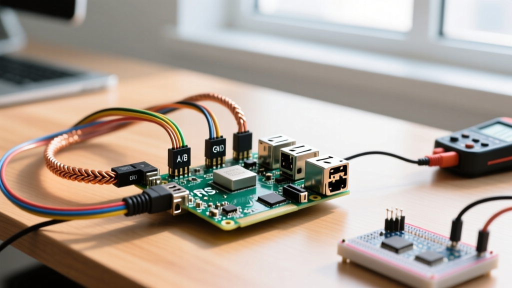
The physical interface of a servo dictates how your microcontroller must be configured. The standard hobby servo uses a 3-pin JST or 2.54mm DuPont connector.
- Ground (GND): Black or Brown wire. Must share a common ground with your microcontroller and power supply.
- Power (VCC): Red wire. Typically 4.8V to 6.0V for standard servos, up to 8.4V for high-voltage (HV) models.
- Signal: Orange, Yellow, or White wire. Carries the PWM or serial data.
The ESP32 3.3V Logic Trap
A frequent point of failure in embedded projects is driving a 5V analog servo directly from an ESP32 GPIO pin. The ESP32 outputs a 3.3V logic HIGH. While the ESP32 LEDC PWM peripheral is highly capable, many analog servo control boards require a minimum of 4.0V to reliably register a logic HIGH on the signal line. If you feed them 3.3V, the servo will either ignore the signal, jitter violently, or draw excessive current as its internal logic floats.
The Fix: Use a bidirectional logic level shifter (like a 74AHCT125 or a dedicated MOSFET-based shifter) to translate the 3.3V PWM signal to 5V. Alternatively, bypass analog PWM entirely and use a serial bus servo (like the Dynamixel or Feetech SCS series), which reliably reads 3.3V UART RX lines without level shifting.
Power Delivery and BECs
Never power a servo rated above 10 kg-cm directly from a microcontroller's onboard 5V regulator. A DS3218 pulling 2.5A at stall will instantly collapse the voltage rail, resetting your ESP32 and potentially frying the onboard AMS1117 LDO. Use a dedicated Buck Electronics Converter (BEC) or a high-current buck module (like an LM2596 set to 5.0V) wired directly to the battery, sharing only the GND and Signal lines with the microcontroller.
Sizing Rule of Thumb and Worked Load Example
Sizing a servo requires calculating the worst-case static torque and applying a dynamic safety factor. Do not rely on horsepower or kilowatt conversions here; servo sizing is strictly about Newton-meters (Nm) or kilogram-centimeters (kg-cm) at the output shaft.
The Rule of Thumb: Calculate the maximum static holding torque at the furthest extension of your lever arm, then multiply by a safety factor of 2.5x to account for dynamic acceleration, friction, and the fact that continuous torque is much lower than stall torque.
Worked Load Example: Robotic Arm Elbow Joint
Assume we are building an arm that must lift a 200g payload. The forearm (from the elbow joint to the gripper) is 15 cm long and weighs 100g itself. We need to size the elbow servo.
- Payload Torque: Force = mass × gravity. 0.2 kg × 9.81 m/s² = 1.96 N. Distance = 0.15 m. Torque = 1.96 N × 0.15 m = 0.294 Nm.
- Arm Weight Torque: The arm's center of mass is roughly halfway (7.5 cm or 0.075 m). 0.1 kg × 9.81 m/s² = 0.98 N. Torque = 0.98 N × 0.075 m = 0.073 Nm.
- Total Static Torque: 0.294 + 0.073 = 0.367 Nm.
- Convert to kg-cm: 0.367 Nm × 10.197 = 3.74 kg-cm.
- Apply Dynamic Safety Factor (2.5x): 3.74 kg-cm × 2.5 = 9.35 kg-cm.
Based on this math, a standard 13 kg-cm MG996R will technically work, but it will operate near its continuous limit, leading to overheating. Selecting a 20 kg-cm digital servo like the DS3218 provides the necessary thermal and mechanical headroom for smooth acceleration without stalling.
Failure Signatures: Hum, Overheat, and Stall
Servos fail in highly specific ways that tell you exactly what is wrong with your circuit or mechanical design. Recognizing these signatures saves hours of debugging.
1. The "Hum" or Jitter
Symptom: The servo vibrates rapidly back and forth by 1 or 2 degrees, accompanied by an audible humming noise, even when the microcontroller is sending a static PWM value.
Causes & Fixes:
- Power Supply Ripple: The voltage is dipping below the servo's internal logic reset threshold (usually ~4.2V) every time the motor kicks on. Add a 470µF electrolytic capacitor across the VCC and GND terminals at the servo.
- Loose Potentiometer: In cheap analog servos, the wiper on the internal potentiometer loses physical contact with the carbon track. The servo loses its position reference and hunts blindly. Replace the servo.
- Ground Loop Noise: High-current devices (like drive motors) sharing a ground wire with the servo signal line are injecting noise into the PWM reading. Route servo signal grounds separately from high-current motor grounds, joining them at a single star point.
2. Overheat and Thermal Shutdown
Symptom: The servo casing becomes too hot to touch (>60°C), and the servo eventually stops responding or emits a faint burning smell.
Causes & Fixes:
- Static Holding Load: Digital servos use high-frequency PWM (up to 300Hz) to the internal DC motor to maintain position. If a heavy load forces the servo just 0.5° off its target, the controller dumps near-stall current (often 2A+) into the windings continuously. Servos are designed for motion, not as static brakes. If your application requires holding a heavy load indefinitely, use a worm-gear drive or a stepper motor with a mechanical brake.
3. Mechanical Stall and Stripping
Symptom: The motor spins audibly inside the casing, but the output spline does not move, or the output shaft feels loose and slips under load.
Causes & Fixes:
- Exceeding Stall Torque: The load exceeded the motor's maximum electromagnetic force. The motor stops, draws maximum current, and risks burning out the H-bridge inside the servo. You must upsize the motor or reduce the lever arm length.
- Gear Stripping: The internal gears (often nylon in standard servos) have sheared teeth. Always specify metal-gear or steel-gear variants (like the MG996R or DS3218) for any joint experiencing shock loads or impacts.
Matching Motor Types to Load Profiles
Choosing the right actuator requires matching the mechanical demand to the motor's inherent physics. Steppers and servos are not interchangeable; they solve fundamentally different problems.
| Load Profile | Best Motor Choice | Why It Wins | Required Controller |
|---|---|---|---|
| High holding torque, low speed, precise angular position (e.g., robotic joints, camera gimbals) | Servo Motor | Closed-loop feedback corrects positional errors caused by external forces; high torque-to-size ratio. | PWM Generator or UART Serial Bus |
| High speed, continuous rotation, precise velocity control (e.g., conveyor belts, CNC spindles) | DC Motor + Encoder | Servos are mechanically limited to ~180°-360° of rotation and overheat at high continuous RPMs. | H-Bridge + PID Controller (e.g., ODrive) |
| High precision, high speed, open-loop acceptable, no positional drift under static load (e.g., 3D printer axes) | Stepper Motor | Maintains position without drawing high continuous current; excellent low-speed smoothness without gearboxes. | Step/Dir Driver (e.g., TMC2209) |
When designing your next embedded system, start with the load profile. If the application demands that the shaft must return to an exact absolute angle after being physically disturbed, the closed-loop nature of the servo is mandatory. For further reading on actuator torque calculations and mechanical advantage, consult the Pololu Servo Torque and Sizing Guide, and for advanced serial bus integration, review the ROBOTIS Dynamixel e-Manual.