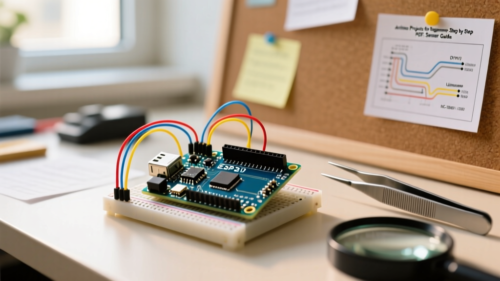
An "RC switch ESP32" project typically pairs an ESP32 microcontroller with a 433MHz RF receiver and the RCSwitch library to decode signals from cheap wireless remote controls and trigger relays. The fastest path to a working, noise-resistant prototype uses an ESP32 DevKit V1, an RXB6 high-sensitivity superheterodyne receiver, and a 5V optocoupler-isolated relay module. This guide gives you the exact hardware specs, wiring pinouts, and compilable code to get it running, followed by a bench-tested debugging framework for when the RF environment fights back.
Hardware BOM and RF Module Specifications
The most common point of failure in 433MHz ESP32 builds is selecting the wrong receiver module. The cheap green modules bundled with remote kits are regenerative receivers; they are highly susceptible to local oscillator drift and broadband noise from switching power supplies. For a reliable RC switch ESP32 build, you must use a superheterodyne receiver.
| Module Model | Architecture | Sensitivity (dBm) | Operating Voltage | Data Rate | Typical Price |
|---|---|---|---|---|---|
| LM393 (Green Board) | Regenerative | -105 dBm | 3.3V - 5.0V | 2.4 Kbps | $1.20 |
| RX470C | Super-Regenerative | -112 dBm | 3.3V - 5.0V | 9.6 Kbps | $2.50 |
| RXB6 (Recommended) | Superheterodyne | -115 dBm | 3.3V - 5.0V | 9.6 Kbps | $3.50 |
| RXB12 | Superheterodyne | -118 dBm | 5.0V Only | 9.6 Kbps | $4.80 |
Wiring the ESP32 to the RXB6 and Relay Module
This build targets the ESP32 DevKit V1 (30-pin, ESP32-WROOM-32 variant). We intentionally avoid GPIOs 0, 2, 5, 12, and 15, which are strapping pins that dictate boot modes. Pulling these high or low during power-on can cause the ESP32 to enter flash download mode or fail to boot entirely (see the Espressif Hardware Design Guidelines for the full strapping pin matrix).
Pin Mapping Table
| Component | Module Pin | ESP32 GPIO | Notes |
|---|---|---|---|
| RXB6 Receiver | VCC | 3V3 | Do not use 5V pin; RXB6 is 3.3V native. |
| RXB6 Receiver | GND | GND | Share common ground with relay. |
| RXB6 Receiver | DATA | GPIO 13 | Safe input pin, no boot conflicts. |
| Relay Module | VCC | VIN (5V) | Requires 5V for the relay coil. |
| Relay Module | GND | GND | Common ground. |
| Relay Module | IN1 | GPIO 27 | Safe output pin. Active LOW. |
Complete RCSwitch ESP32 Code (Target: ESP32 DevKit V1)
This code uses the RCSwitch library. It includes pulse-length validation to reject broadband RF noise, which is critical when operating in environments with LED drivers or switching power supplies that emit 433MHz harmonics.
#include

// --- PIN DEFINITIONS ---
const int RF_RECEIVE_PIN = 13;
const int RELAY_PIN = 27;

// --- RF CONFIGURATION ---
// Replace with your specific remote's 24-bit decimal code
const unsigned long TARGET_RF_CODE = 5592405;
const int ACCEPTABLE_PULSE_LENGTH = 190; // Typical for PT2262 remotes
const int PULSE_TOLERANCE = 30;          // +/- 30us tolerance

RCSwitch mySwitch = RCSwitch();
bool relayState = false;
unsigned long lastDebounceTime = 0;
const long debounceDelay = 500; // 500ms debounce

void setup() {
  Serial.begin(115200);

  // Initialize Relay Pin
  pinMode(RELAY_PIN, OUTPUT);
  digitalWrite(RELAY_PIN, HIGH); // Active LOW relays start OFF when HIGH

  // Initialize RCSwitch on GPIO 13
  mySwitch.enableReceive(RF_RECEIVE_PIN);

  Serial.println("[SYS] RC Switch ESP32 Initialized.");
  Serial.printf("[SYS] Target Code: %lu\n", TARGET_RF_CODE);
}

void loop() {
  if (mySwitch.available()) {
    unsigned long value = mySwitch.getReceivedValue();
    int pulseLength = mySwitch.getReceivedDelay();
    int bitLength = mySwitch.getReceivedBitlength();

    // 1. Filter out spurious noise based on pulse length
    if (pulseLength < (ACCEPTABLE_PULSE_LENGTH - PULSE_TOLERANCE) ||
        pulseLength > (ACCEPTABLE_PULSE_LENGTH + PULSE_TOLERANCE)) {
      Serial.printf("[WARN] Noise rejected: Pulse length %dus out of bounds.\n", pulseLength);
      mySwitch.resetAvailable();
      return;
    }

    // 2. Filter out invalid decodes
    if (value == 0) {
      Serial.println("[ERR] Failed to decode: Unknown encoding.");
      mySwitch.resetAvailable();
      return;
    }

    // 3. Debounce and match target code
    if (value == TARGET_RF_CODE && (millis() - lastDebounceTime) > debounceDelay) {
      lastDebounceTime = millis();
      relayState = !relayState;
      digitalWrite(RELAY_PIN, relayState ? LOW : HIGH); // Active LOW logic
      Serial.printf("[ACT] Relay toggled: %s | Code: %lu | Pulse: %dus\n",
                    relayState ? "ON" : "OFF", value, pulseLength);
    } else if (value != TARGET_RF_CODE) {
      Serial.printf("[INF] Ignored foreign code: %lu\n", value);
    }

    mySwitch.resetAvailable();
  }
}
Debugging: Spurious Decodes and RF Noise Issues
When your RC switch ESP32 build fails to trigger, or triggers randomly without you pressing the remote, the issue is almost always physical layer RF noise or a boot-strapping conflict. Here are the first three things to check when the system fails:
- The Quarter-Wave Antenna: The RXB6 and your handheld remote both require a 17.3cm (6.8 inch) straight wire antenna for 433MHz. The formula is
(Speed of Light / Frequency) * 0.25 * Velocity Factor. Without this exact length of uninsulated copper wire soldered to the ANT pad, your range drops from 50 meters to about 2 meters, and the signal-to-noise ratio collapses. - GPIO 12 Strapping Pin Conflict: If you wired the receiver to GPIO 12 and the ESP32 fails to boot or spits out brownout detector errors, it is because GPIO 12 dictates the flash voltage. The internal pull-up/pull-down state of the RXB6 data line during power-on forces the ESP32 into the wrong boot mode. Move the data line to GPIO 13 or 14.
- Relay Coil Flyback Noise: If the ESP32 resets exactly when the relay clicks, your 5V USB power supply is browning out under the inductive spike of the relay coil. Ensure your relay module has an optocoupler (the black 4-pin IC near the input pins) and a flyback diode across the coil (standard on most blue 5V relay modules).
Diagnosing Exact Serial Error Strings
If your serial monitor is outputting specific errors, use this ranked cause list to fix them:
[WARN] Noise rejected: Pulse length Xus out of bounds.
Cause: The receiver is picking up broadband EMI from LED drivers, laptop chargers, or solar inverters. TheRCSwitchlibrary locks onto a false preamble.
Fix: Measure the pulse length of the noise. If it's consistently clustering around a specific value, narrow thePULSE_TOLERANCEvariable in the code from 30 to 15.[ERR] Failed to decode: Unknown encoding.
Cause: The receiver detected a valid sync bit but the payload bits were corrupted by multipath interference or a dying 12V battery in the handheld remote.
Fix: Replace the A23 (12V) battery in the remote. Weak batteries cause the remote's internal oscillator to drift, altering the pulse width just enough to fail the ESP32's decode threshold.Received value: 0 | Protocol: 0(Native RCSwitch output if debug is enabled)
Cause: You are using a remote with an unsupported encoding scheme (e.g., rolling code or a proprietary Protocol 6+ variant not natively mapped in the standardRCSwitchlibrary).
Fix: Use theAdvancedReceiverexample in the RCSwitch library to dump raw timings, or switch to theESPiLightlibrary which supports a wider array of Pilight protocols.
Extending or Simplifying the Build
Depending on your end goal, you may need to scale this RC switch ESP32 project up for home automation, or strip it down for a standalone appliance.
How to Extend (Smart Home Integration)
To bridge this RF receiver into Home Assistant or Node-RED, add the PubSubClient library. In the if (value == TARGET_RF_CODE) block, publish the state to an MQTT topic (e.g., home/switch/livingroom/state). Because the ESP32 has dual cores, you can pin the WiFi/MQTT stack to Core 1 and the RF interrupt decoding to Core 0 using xTaskCreatePinnedToCore, ensuring that heavy network traffic never drops incoming 433MHz packets.
How to Simplify (No-Code Alternative)
If you realize you don't actually need WiFi logging, OTA updates, or MQTT integration, drop the ESP32 entirely. Purchase a 433MHz RF Relay Receiver Module with Learning Button (often sold as "KR2201" or generic 12V RF relay boards). These cost about $6, feature a physical button to pair the remote directly to the relay's onboard decoder chip, and require zero programming. They run purely on hardware logic and are significantly more robust against RF noise than a software-decoded microcontroller.