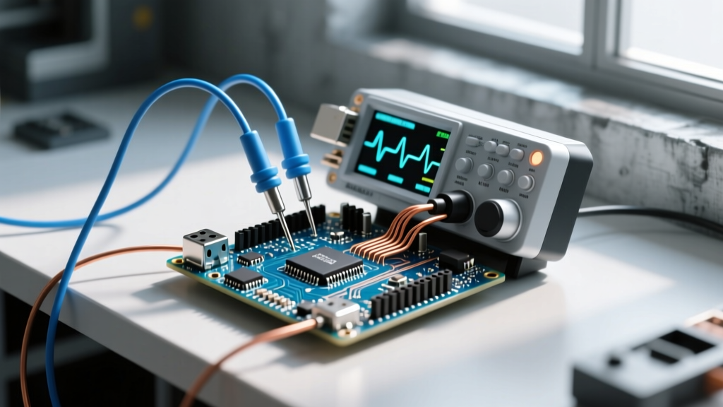
The Raspberry Pi 40-pin header is a 3.3V LVTTL (Low Voltage Transistor-Transistor Logic) environment. Feeding it 5V logic or misidentifying ground pins will instantly destroy the SoC. Before you wire a single sensor, you must know whether your code uses BCM (Broadcom) channel numbers or physical board pin numbers, and how your wire colors map to safe DC logic standards.
The 40-Pin Header: Physical vs BCM Numbering Table
The table below maps the physical header layout (looking down at the board with USB ports facing you, header on the top right) to the Broadcom (BCM) GPIO numbers used in Python/C. Standard: Always use BCM numbering in software (e.g., GPIO.setmode(GPIO.BCM) in RPi.GPIO) to maintain compatibility across Pi 3, 4, and 5 models.
| Phys | BCM | Function / Notes | || | Function / Notes | BCM | Phys |
|---|---|---|---|---|---|---|
| 1 | - | 3.3V Power (Max 50mA draw) | || | 5V Power (Input from PSU) | - | 2 |
| 3 | 2 | GPIO 2 (I2C1 SDA, 1.8kΩ pull-up) | || | 5V Power | - | 4 |
| 5 | 3 | GPIO 3 (I2C1 SCL, 1.8kΩ pull-up) | || | Ground | - | 6 |
| 7 | 4 | GPIO 4 (GPCLK0) | || | GPIO 14 (UART0 TXD) | 14 | 8 |
| 9 | - | Ground | || | GPIO 15 (UART0 RXD) | 15 | 10 |
| 11 | 17 | GPIO 17 (General Purpose) | || | GPIO 18 (Hardware PWM0) | 18 | 12 |
| 13 | 27 | GPIO 27 (General Purpose) | || | Ground | - | 14 |
| 15 | 22 | GPIO 22 (General Purpose) | || | GPIO 23 (General Purpose) | 23 | 16 |
| 17 | - | 3.3V Power | || | GPIO 24 (General Purpose) | 24 | 18 |
| 19 | 10 | GPIO 10 (SPI0 MOSI) | || | Ground | - | 20 |
| 21 | 9 | GPIO 9 (SPI0 MISO) | || | GPIO 25 (General Purpose) | 25 | 22 |
| 23 | 11 | GPIO 11 (SPI0 SCLK) | || | GPIO 8 (SPI0 CE0) | 8 | 24 |
| 25 | - | Ground | || | GPIO 7 (SPI0 CE1) | 7 | 26 |
| 27 | 0 | ID_SD (I2C ID EEPROM, Do Not Use) | || | ID_SC (I2C ID EEPROM, Do Not Use) | 1 | 28 |
| 29 | 5 | GPIO 5 (General Purpose) | || | Ground | - | 30 |
| 31 | 6 | GPIO 6 (General Purpose) | || | GPIO 12 (Hardware PWM0) | 12 | 32 |
| 33 | 13 | GPIO 13 (Hardware PWM1) | || | Ground | - | 34 |
| 35 | 19 | GPIO 19 (SPI1 MISO / I2S) | || | GPIO 16 (General Purpose) | 16 | 36 |
| 37 | 26 | GPIO 26 (General Purpose) | || | GPIO 20 (SPI1 MOSI / I2S) | 20 | 38 |
| 39 | - | Ground | || | GPIO 21 (SPI1 SCLK / I2S) | 21 | 40 |
Source reference: For interactive visual mapping and HAT-specific overlays, consult the definitive Pinout.xyz database.
Wiring Standards: Pi GPIO Logic vs NEC/IEC Mains Color Codes
A frequent and dangerous bench mistake is using leftover mains wiring (THHN or NM-B offcuts) for low-voltage Pi projects. The color codes for AC mains and DC logic are fundamentally incompatible, and crossing them can lead to lethal faults if your Pi project interfaces with mains-relay modules.
Regional Mains Standards vs. Pi DC Standard
- NEC (US/Canada Mains): Green/Bare = Earth Ground; White = Neutral; Black/Red = Hot. Never use White for Pi Ground.
- IEC 60446 (EU/UK Mains): Green-Yellow = Earth; Blue = Neutral; Brown = Live. Never use Blue for Pi I2C SDA.
- Pi DC Logic Standard (De Facto): Red = 5V; Orange = 3.3V; Black = Ground (GND); Yellow = SDA/Signal; Green = SCL/Clock; Blue = SPI/Chip Select.
Which standard applies to you? For the 40-pin header, you must strictly follow the Pi DC Logic Standard. If your project leaves the breadboard and enters a junction box with a 120V/230V AC relay, the mains side of that relay must be wired using your local NEC or IEC color codes, and the two systems must be separated by an optocoupler or a properly rated relay module with physical isolation gaps.
The "Rows People Get Wrong" Trap Guide
Not all pins on the header are created equal. Frying a Pi usually happens because a builder assumed all pins tolerate 5V or that all grounds are equal. Here are the specific rows that destroy hardware:
- Physical Pin 1 (3.3V) vs Pin 2 (5V): The 3.3V rail is generated by an onboard LDO regulator with a strict ~50mA limit. If you connect a servo or a string of WS2812B LEDs to Pin 1, you will brownout the Pi or melt the regulator. Rule: High-current 5V loads go to Pin 2 or 4, and must be powered by a PSU capable of 3A+.
- Physical Pins 27 & 28 (ID_SD / ID_SC): These are BCM 0 and 1. They are reserved exclusively for reading the EEPROM on Raspberry Pi HATs. They have specific pull-up configurations tied to the SoC boot sequence. Rule: Never use these for general GPIO or I2C sensors.
- Physical Pins 8 & 10 (UART TX/RX): BCM 14 and 15. By default, the Pi routes the Linux serial console to these pins. If you wire a sensor here without disabling the serial console in
raspi-config, the Pi will spit boot logs into your sensor, potentially causing erratic behavior or damage. Rule: Disable serial console login before using hardware UART. - The "5V Tolerant" Myth: No pin on the Pi 3, 4, or 5 is 5V tolerant. The absolute maximum voltage on any BCM GPIO pin is 3.6V. Feeding a 5V Arduino signal directly into Pi BCM 17 will permanently short the internal ESD diodes, destroying the SoC. Rule: Always use a logic level shifter (like the BSS138 MOSFET bidirectional shifter) when interfacing 5V logic.
Decision Path: Which Pin Should You Actually Use?
Stop guessing which GPIO to assign. Use this decision tree to select the exact pin and the required supporting components for your specific hardware task.
| If your task is... | Then use this Pin (BCM) | Required Supporting Parts / Configuration |
|---|---|---|
| Reading a simple push button | BCM 17 (Phys 11) | 10kΩ pull-up resistor to 3.3V (or enable internal pull-up in software). No external parts needed if using internal. |
| Driving a standard 5mm LED | BCM 27 (Phys 13) | 330Ω current-limiting resistor in series. (3.3V - 2.0V LED drop) / 0.004A = 325Ω. |
| Switching a 12V Relay Module | BCM 22 (Phys 15) | 2N2222 NPN transistor, 1kΩ base resistor, 1N4007 flyback diode across relay coil. Do not drive relay coils directly from GPIO. |
| Reading an I2C Sensor (BME280) | BCM 2 (SDA) & BCM 3 (SCL) | No external pull-ups needed (Pi has 1.8kΩ onboard). Ensure sensor is set to 3.3V VCC. |
| High-Speed ADC / DAC (SPI) | BCM 10 (MOSI), 9 (MISO), 11 (SCLK), 8 (CE0) | Keep SPI trace wires under 10cm. Add a 100nF decoupling capacitor across the ADC VCC/GND pins. |
| Dimming a MOSFET / Motor | BCM 18 (Phys 12) | Hardware PWM0. Use a logic-level MOSFET (e.g., IRLZ44N) with a 10kΩ gate-to-source pulldown resistor. |
Safe Interpretation When Silk Screen Markings Fade
On older Pi 1 Model B+ or Pi 2 boards, or boards exposed to high-heat industrial environments, the white silk-screen text next to the GPIO header often fades or flakes off. If you cannot read the pin labels, do not guess. Use these three hardware-level verification methods to safely identify your pins before applying power.
- The Square Pad Rule (Pin 1 Identification): Flip the board over or look closely at the solder joints on the underside of the header. Pin 1 is always terminated with a square solder pad. Every other pin on the header uses a round solder pad. Pin 1 is always the 3.3V supply.
- The USB Shield Continuity Test: Set your multimeter to continuity mode (the diode/beep setting). Place one probe on the metal shield of the USB port or the Ethernet jack. Touch the other probe to the header pins. The pins that beep (read < 1 ohm) are your Ground pins. This works because the USB/Ethernet shields are bonded to the primary DC ground plane.
- The Orientation Anchor: Place the board flat on your desk with the USB and Ethernet ports facing towards your stomach. The GPIO header is on the top-right edge. The top-left pin of that header (closest to the Ethernet port) is always Physical Pin 1. The top-right pin is Physical Pin 2. Count down in a zig-zag pattern from there.