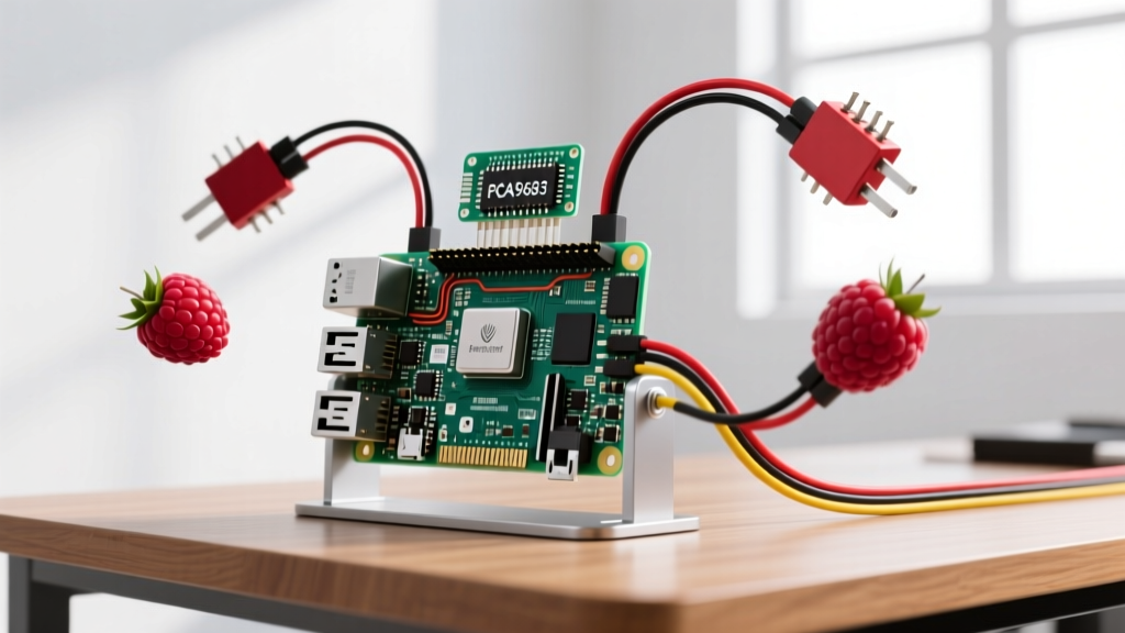
The Raspberry Pi FM transmitter works by hijacking the hardware clock generator on GPIO 4 (Physical Pin 7) and driving it at roughly 100 MHz. By rapidly modulating the clock divider via Direct Memory Access (DMA), the Pi emits an RF signal in the commercial FM broadcast band (87.5–108 MHz) without any external radio hardware. While pre-compiled binaries like PiFmRds handle the heavy lifting, understanding the bare-metal clock manipulation is critical when your broadcast fails, throws memory errors, or causes harmonic interference.
Project Spec Sheet & Parts List
Building a reliable transmitter requires more than just the board. Impedance mismatches and power supply noise will destroy your audio quality and range.
| Component | Exact Model / Specification | Purpose | Est. Cost |
|---|---|---|---|
| Microcontroller | Raspberry Pi 4 Model B (4GB) | Compute & Clock Generation (BCM2711) | $55.00 |
| Antenna | 20 AWG Solid Copper Wire (75 cm) | Quarter-wave monopole for ~100 MHz | $0.50 |
| Power Supply | Official 27W USB-C PD (5.1V / 3A) | Prevents brownouts during RF spikes | $12.00 |
| Audio Input | USB Audio Capture Card (3.5mm) | Bypasses noisy onboard analog audio | $8.00 |
| Software Library | bcm2835 C Library (v1.73+) | Direct register access for GPCLK0 | Free |
Hardware Wiring & Pin Mapping
The Pi’s FM transmission relies entirely on GPCLK0. Do not use PWM pins; software PWM is far too slow and jittery to generate a clean 100 MHz carrier wave.
| Physical Pin | BCM GPIO | Function | Connection |
|---|---|---|---|
| Pin 7 | GPIO 4 | GPCLK0 (ALT0) | 75cm Copper Wire (Antenna) |
| Pin 2 | 5V | Power | Not used directly for RF, but powers board |
| Pin 6 | GND | Ground | Ground plane reference (optional radial) |
The Core C Code: Driving GPCLK0 for RF
Before you can modulate audio, you must establish the carrier wave. The following C code uses the bcm2835 library to map the Pi's peripheral memory, configure GPIO 4 as an alternate clock function, and lock the PLLA to output a 100.0 MHz carrier.
Compile with: gcc -o fm_carrier fm_carrier.c -l bcm2835 -lm
#include <bcm2835.h>
#include <stdio.h>
#include <stdlib.h>
#include <unistd.h>

// TARGET BOARD: Raspberry Pi 4 Model B & Pi 3B+ (BCM2711 / BCM2837)
// NOTE: This code will NOT run on Raspberry Pi 5 (RP1 chip architecture)

#define RF_PIN RPI_V2_GPIO_P1_07  // Physical Pin 7, BCM GPIO 4 (GPCLK0)
#define CM_GP0CTL 0x7e101070      // Clock Manager GP0 Control Register
#define CM_GP0DIV 0x7e101074      // Clock Manager GP0 Divider Register

int main() {
    // Initialize library and map /dev/mem
    if (!bcm2835_init()) {
        fprintf(stderr, "FATAL: bcm2835_init failed. Are you running with sudo?\n");
        return EXIT_FAILURE;
    }

    // Set GPIO 4 to ALT0 function (GPCLK0)
    bcm2835_gpio_fsel(RF_PIN, BCM2835_GPIO_FSEL_ALT0);

    // Access Clock Manager registers via peripheral pointers
    volatile uint32_t *clk_ctl = (uint32_t *)((char *)bcm2835_peripherals + (CM_GP0CTL - 0x7e000000));
    volatile uint32_t *clk_div = (uint32_t *)((char *)bcm2835_peripherals + (CM_GP0DIV - 0x7e000000));

    // Stop clock, set source to PLLA (500MHz base), start clock
    *clk_ctl = 0x5A000000 | (1 << 5); // Password + Stop bit
    usleep(1000);

    // Divider = 5 (500MHz / 5 = 100MHz carrier)
    *clk_div = 0x5A000000 | (5 << 12);

    // Start with PLLA source (bits 0-3 = 0001)
    *clk_ctl = 0x5A000011;

    printf("Transmitting 100.0 MHz carrier on GPIO 4. Press Ctrl+C to stop.\n");

    // In a full transmitter, a DMA loop modulates clk_div here based on audio samples
    while(1) {
        sleep(1);
    }

    bcm2835_close();
    return EXIT_SUCCESS;
}
Debugging: Exact Error Strings & Ranked Causes
When working directly with hardware registers, the OS will aggressively block you if permissions or memory mappings are wrong. Here is how to diagnose the most common fatal crashes.
1. bcm2835_init: mmap of /dev/mem failed: Operation not permitted
- Cause A (Most Likely): You forgot to run the executable with
sudo. Direct memory access requires root. - Cause B: Kernel Lockdown is enabled. If you are on a newer Raspberry Pi OS with secure boot or lockdown mode active,
/dev/memis restricted even for root. Fix by editing/boot/firmware/cmdline.txtand appendinglockdown=none.
2. Segmentation fault (core dumped) immediately upon execution
- Cause A: You are running this on a Raspberry Pi 5. The Pi 5 uses the RP1 southbridge, meaning the BCM2711 memory addresses (like
0x7e101070) map to empty space or protected RAM, causing an instant segfault. - Cause B: Outdated
bcm2835library. Versions older than 1.68 do not recognize the BCM2711 peripheral base address on the Pi 4, resulting in a null pointer dereference.
3. clock manager PLLA not locked (Printed via dmesg)
- Cause: The Phase Locked Loop failed to stabilize. This is almost always a power supply issue. The RF draw causes micro-brownouts on the 3.3V rail, dropping the PLL out of lock. Switch to an official USB-C PD power supply and avoid cheap phone chargers.
First Three Things to Check When It Fails
If the code compiles and runs without errors, but your radio picks up only static or nothing at all, run through this physical-layer checklist:
- Verify Antenna Length & Impedance: A random piece of wire will result in massive VSWR (Voltage Standing Wave Ratio), reflecting power back into the Pi. For 100 MHz, the wavelength is 3 meters. A quarter-wave monopole must be exactly 75 cm. If using a shorter wire, range will drop from ~100 meters to under 2 meters.
- Check Audio ALSA Routing: The Pi’s onboard 3.5mm jack shares a PWM circuit with the analog video out and is notoriously noisy. If using PiFmRds, ensure your audio is routed correctly via ALSA by running
aplay -land passing the correct hardware ID (e.g.,hw:1,0for a USB sound card). - Measure the 3.3V Rail: Use a multimeter to check the voltage between Pin 1 (3.3V) and Pin 6 (GND) while transmitting. If it drops below 3.1V under load, the clock generator will jitter, and your FM signal will sound like a distorted, buzzing mess.
Extending or Simplifying the Build
Writing your own DMA loop to modulate the clock divider in real-time is a massive undertaking. Here is how to adjust the project scope based on your needs.
make, and use their optimized binary. It handles DMA, audio resampling, and RDS (Radio Data System) text broadcasting out of the box.
Extend the Build (Harmonic Filtering): The Pi outputs a square wave, not a sine wave. This means you are broadcasting heavy harmonics at 300 MHz, 500 MHz, and beyond, which can interfere with local aviation or emergency bands. Extend your build by soldering a simple 3rd-order LC low-pass filter (using surface-mount inductors and NP0/C0G capacitors) between GPIO 4 and the antenna to cut off everything above 110 MHz.
Frequently Asked Questions
Is building a Raspberry Pi FM transmitter legal under FCC rules?
In the United States, intentional broadcasting on the FM band without a license is governed by FCC Part 15. Under Section 15.239, operation in the 88–108 MHz band is permitted only if the field strength does not exceed 250 microvolts/meter at a distance of 3 meters. In practice, this means a bare Pi with a 75cm wire antenna broadcasting at full power exceeds legal limits. To be strictly compliant, you must heavily attenuate the output or use a shielded enclosure with a certified low-power FM module. Always defer to your local regulatory body (Ofcom in the UK, FCC in the US).
Why does my Raspberry Pi FM transmitter interfere with WiFi?
The Pi’s WiFi operates at 2.4 GHz and 5 GHz. The raw square-wave clock output from GPIO 4 contains high-frequency harmonics. The 24th harmonic of a 100 MHz carrier is exactly 2.4 GHz. Because the Pi lacks internal shielding on the GPIO pins, these harmonics radiate directly into the onboard WiFi/BT chip. Moving the antenna away from the Pi board, wrapping the Pi in a grounded metal enclosure (with the antenna protruding via a bulkhead SMA connector), or adding the aforementioned low-pass filter will resolve the WiFi drops.
Can I use a Raspberry Pi 5 for an FM transmitter project?
No, not with existing software. The Raspberry Pi 5 replaced the Broadcom SoC’s direct peripheral access with the RP1 southbridge chip. The memory addresses for the clock manager and DMA controllers are entirely different, and the RP1 handles GPIO multiplexing via a PCIe link rather than direct memory mapping. Neither bcm2835 nor PiFmRds will compile or run on a Pi 5 without a ground-up rewrite of the hardware abstraction layer. Stick to a Pi 4 or Pi 3 for this project.
How far will the Raspberry Pi FM transmitter reach with a wire antenna?
With a properly tuned 75cm quarter-wave antenna, a clear line of sight, and a sensitive car radio receiver, you can expect a usable range of 50 to 100 meters. Indoors, structural steel and rebar will drop this to 10–15 meters. If you attach a 10cm piece of wire, the impedance mismatch reduces the radiated power by over 90%, limiting your range to a single room. Range is a function of antenna efficiency, not just raw compute power.