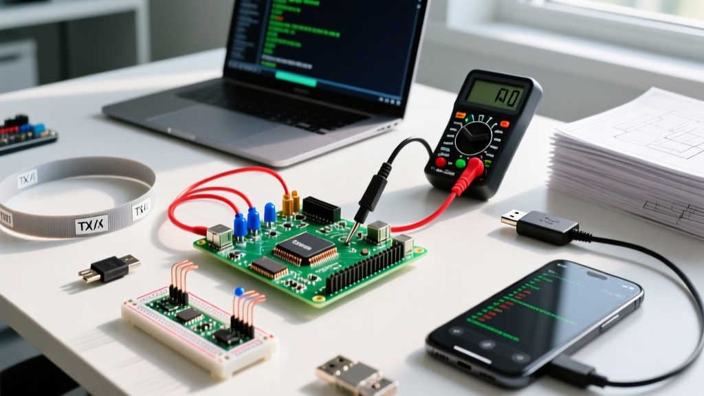
The Direct Answer: Pulse Width Modulation on Raspberry Pi
If you are looking to implement pulse width modulation Raspberry Pi projects, the short answer is that the Raspberry Pi SoC features exactly four dedicated hardware PWM pins: GPIO 12, 13, 18, and 19. While you can bit-bang software PWM on any of the 26 available GPIO pins, software PWM suffers from severe frequency jitter under Linux OS load. For driving inductive loads like 4-pin PC cooling fans, dimming high-power LED strips, or controlling servos without jitter, you must use the dedicated hardware PWM channels paired with a logic-level MOSFET.
RPi Hardware PWM Pin Mapping & Specifications
Before wiring your breadboard, you need to know which physical pins route to the SoC's internal PWM peripherals. The BCM2711 (Pi 4) and BCM2712 (Pi 5) share the same alternate function mappings for PWM. Below is the definitive reference table for hardware PWM routing.
| BCM GPIO | Physical Pin | Alt Function | PWM Channel | Max Stable Freq | Best Use Case |
|---|---|---|---|---|---|
| 12 | 32 | ALT0 | PWM0 | ~100 kHz | Audio DAC, LED dimming |
| 13 | 33 | ALT0 | PWM1 | ~100 kHz | Secondary LED, Servo 2 |
| 18 | 12 | ALT5 | PWM0 | ~100 kHz | PWM Fans, Motor control |
| 19 | 35 | ALT5 | PWM1 | ~100 kHz | Secondary Fan, Servo 1 |
Source: Raspberry Pi Official Hardware Documentation. Note that PWM0 and PWM1 share internal channels; using GPIO 12 and 18 simultaneously will force them to share the same frequency, though duty cycles can remain independent.
Project Build: Driving a 12V PWM Load via Logic-Level MOSFET
The Pi's GPIO pins output 3.3V at a maximum of 16mA. You cannot drive a 12V fan or a 5A LED strip directly. We will use a logic-level N-channel MOSFET to switch the high-current load.
Parts List
- Board: Raspberry Pi 4 Model B (4GB) or Raspberry Pi 5 (8GB) running Pi OS Bookworm.
- MOSFET: IRLZ44N or IRLB8721 (Must be logic-level. Standard IRF520 modules will fail to fully turn on at 3.3V and will overheat).
- Gate Resistor: 220Ω (Limits transient inrush current to the GPIO pin during gate charging).
- Pull-down Resistor: 10kΩ (Prevents the MOSFET from turning on while the Pi is booting and GPIOs are floating).
- Flyback Diode: 1N4007 or 1N5819 (Required across inductive loads like fans to prevent voltage spikes from killing the MOSFET).
- Load: 12V 4-pin PWM cooling fan or 12V LED strip.
- Power Supply: 12V 5A DC switching supply.
Wiring & Pin Mapping Table
| Component Node | Connects To | Wire Gauge / Note |
|---|---|---|
| Pi GPIO 18 (Physical 12) | 220Ω Resistor (Input) | 24 AWG jumper |
| 220Ω Resistor (Output) | MOSFET Gate (G) | 24 AWG jumper |
| MOSFET Gate (G) | 10kΩ Resistor to GND | Pull-down to Pi GND |
| MOSFET Source (S) | Pi GND & 12V PSU GND | 18 AWG (Common ground is critical) |
| MOSFET Drain (D) | Fan/LED Negative (-) | 18 AWG |
| Fan/LED Positive (+) | 12V PSU VCC (+) | 18 AWG |
| Flyback Diode (Cathode) | Fan/LED Positive (+) | Stripe points to VCC |
| Flyback Diode (Anode) | MOSFET Drain (D) | Across the load |
Assembly Steps
- De-energize: Ensure the Pi and the 12V PSU are completely unplugged.
- Establish Common Ground: Connect the Pi's physical Pin 6 (GND) to the 12V PSU's negative terminal. If you skip this, the PWM signal has no reference voltage and the MOSFET will not switch.
- Wire the Gate Drive: Connect GPIO 18 through the 220Ω resistor to the MOSFET Gate. Solder or breadboard the 10kΩ resistor between the Gate and Source (GND).
- Wire the Load: Connect the 12V PSU positive to your load. Connect the load's negative return to the MOSFET Drain.
- Install Protection: Place the flyback diode in parallel with the load, ensuring the cathode stripe faces the 12V positive side.
- Verify: Use a multimeter in continuity mode to verify there are no shorts between the 12V VCC and the Pi's 3.3V/5V rails.
Complete Python Control Code (Bookworm Compatible)
This script targets Raspberry Pi OS Bookworm using the modern gpiozero library, which relies on the lgpio backend natively. It includes explicit error handling for the most common PWM pin and permission faults. For deeper API reference, consult the gpiozero PWMLED documentation.
import sys
import time
from gpiozero import PWMLED
from gpiozero.exc import PinPWMUnsupported, GPIOPinInUse

# Target: Raspberry Pi 4/5 (Bookworm OS)
# GPIO 18 is Hardware PWM0
PWM_PIN = 18
FREQ_HZ = 1000  # 1kHz is standard for 4-pin PC fans

def main():
    fan = None
    try:
        # Initialize hardware PWM on the dedicated pin
        fan = PWMLED(PWM_PIN, frequency=FREQ_HZ)
        print(f'PWM initialized on GPIO {PWM_PIN} at {FREQ_HZ}Hz')

        # Ramp up duty cycle from 0% to 100% in 10% increments
        for duty in range(0, 101, 10):
            fan.value = duty / 100.0
            print(f'Duty Cycle: {duty}%')
            time.sleep(0.5)

        # Hold at 100% for 5 seconds
        fan.on()
        time.sleep(5)

    except PinPWMUnsupported:
        print(f'Error: Hardware PWM not supported on GPIO {PWM_PIN}.')
        print('Verify you are using a dedicated PWM pin (12, 13, 18, or 19).')
        sys.exit(1)
    except GPIOPinInUse:
        print(f'Error: GPIO {PWM_PIN} is currently in use by another process.')
        print('Check for conflicting dtoverlay settings in config.txt.')
        sys.exit(1)
    except KeyboardInterrupt:
        print('\nInterrupt received. Stopping PWM...')
    finally:
        # Safe cleanup to ensure MOSFET turns off
        if fan is not None:
            try:
                fan.off()
                fan.close()
                print('GPIO resources released safely.')
            except Exception as e:
                print(f'Cleanup warning: {e}')

if __name__ == '__main__':
    main()
Debugging: First Three Things to Check When PWM Fails
When your load doesn't spin, light up, or throws a Python exception, don't start rewriting code. Hardware and OS-level conflicts cause 90% of Pi PWM failures. Here is your ranked decision path.
1. The "Cannot determine SOC peripheral base address" Error
Exact Error String: RuntimeError: Cannot determine SOC peripheral base address or RuntimeError: This module can only be run on a Raspberry Pi!
- Cause: You are using the deprecated
RPi.GPIOlibrary on a Raspberry Pi 5. The Pi 5 uses the RP1 southbridge chip, which completely changed the memory mapping for GPIO.RPi.GPIOhardcodes the old BCM283x memory addresses and will instantly crash on Pi 5. - Fix: Uninstall
RPi.GPIO. Refactor your code to usegpiozero(as shown above) orrpi-lgpio. If you absolutely must use legacy code, install the compatibility shim viasudo apt install rpi-rp1-gpio, but migrating togpiozerois the permanent fix.
2. The MOSFET is Overheating or Barely Switching
Symptom: The MOSFET gets too hot to touch at partial duty cycles, or the 12V fan only spins at 50% speed even when the code outputs 100%.
- Cause: You used a standard-level MOSFET (like the ubiquitous IRF520 found in cheap blue breakout boards) instead of a logic-level MOSFET. The IRF520 requires 10V on the gate to fully open its channel (low Rds(on)). At the Pi's 3.3V, it operates in the linear (resistive) region, acting like a giant heater rather than a switch.
- Fix: Check the datasheet for the Vgs(th) (Gate-Source Threshold Voltage) and the Rds(on) test conditions. You need a MOSFET that specifies an Rds(on) at Vgs = 2.5V or 4.5V. The IRLZ44N, IRLB8721, or FQP30N06L are correct choices.
3. The "PinPWMUnsupported" or Jittery Servo/Fan
Exact Error String: gpiozero.exc.PinPWMUnsupported: Pin PWM not supported on this pin
- Cause: You assigned a non-hardware PWM pin (like GPIO 17 or 27) while using a backend configuration that strictly demands hardware PWM, or you are experiencing severe software PWM jitter because the Linux kernel is scheduling background tasks (like cron jobs or network polling) that interrupt the bit-banging loop.
- Fix: Move your signal wire to GPIO 12, 13, 18, or 19. If you must use a different pin for software PWM and need stability, isolate the CPU core using
isolcpusincmdline.txt, or offload the PWM generation to an external I2C module like the PCA9685.
Scaling the Build: Extending and Simplifying
Depending on your final application, you may need to scale this circuit up for industrial loads or down for simple bench testing.
How to Extend (High Current & High Frequency)
If you are driving a massive 50A LED array or switching at ultrasonic frequencies (>20kHz) to eliminate audible coil whine, the Pi's GPIO cannot charge and discharge the MOSFET's gate capacitance fast enough. The 220Ω resistor will form a low-pass RC filter with the gate capacitance, rounding off your square wave and causing massive switching losses.
- The Upgrade: Insert a dedicated gate driver IC between the Pi and the MOSFET. A TC4420 or MCP1402 takes the 3.3V logic signal and outputs a high-current (6A peak) 5V or 12V pulse directly into the gate. This achieves rise times in the nanosecond range, keeping the MOSFET cool even at 100kHz.
How to Simplify (Bench Testing)
If you are just learning the concepts and don't have a 12V PSU or high-power load on hand, strip the circuit down to its bare minimum.
- The Downgrade: Remove the MOSFET, the 12V PSU, and the flyback diode. Connect a standard 5mm LED in series with a 330Ω current-limiting resistor directly between GPIO 18 and physical Pin 6 (GND). The Python code remains exactly the same. You will visually verify the PWM duty cycle changes via the LED's perceived brightness, allowing you to debug your software logic before introducing high-current electrical hazards.