
Project Overview & Hardware Specifications
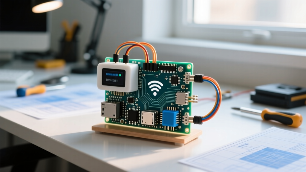
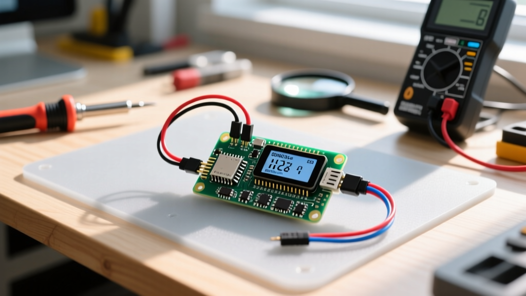
When tackling serious pi pico projects, moving beyond simple LED blinks to robust I2C bus management is the critical leap from hobbyist to engineer. This build creates a standalone environmental data logger using the Raspberry Pi Pico W. It reads temperature, humidity, and pressure from a BME280 sensor, renders the telemetry to a local SSD1306 OLED, and logs the data to the Pico's internal LittleFS filesystem.
The RP2040 microcontroller at the heart of the Pico W features two hardware I2C controllers (i2c0 and i2c1). Unlike software bit-banging, hardware I2C handles clock stretching and NACKs gracefully, but it still requires strict adherence to bus capacitance and pull-up resistor limits. Before wiring anything, review the electrical constraints of the RP2040's I2C implementation below.
RP2040 I2C Bus Electrical & Timing Specifications
| Parameter | Standard Mode (100kHz) | Fast Mode (400kHz) | RP2040 Hardware Limit |
|---|---|---|---|
| Max Bus Capacitance | 400 pF | 400 pF | ~500 pF (degrades rise time) |
| Pull-up Resistor (3.3V) | 4.7kΩ - 10kΩ | 2.2kΩ - 4.7kΩ | Min 1.5kΩ (to stay under 3mA sink) |
| SDA/SCL Rise Time | 1000 ns max | 300 ns max | Depends on R_pullup × C_bus |
| Clock Low Timeout | None (Standard) | SMBus: 25ms | Configurable via I2C_TIMEOUT reg |
Source: NXP I2C-bus specification and user manual (UM10204) cross-referenced with the RP2040 datasheet.
Parts List & Pin Mapping Matrix
For this build, we are using STEMMA QT / Qwiic compatible boards to eliminate breadboard contact resistance, which is a frequent culprit of I2C dropouts in prototype pi pico projects.
Bill of Materials (BOM)
- Microcontroller: Raspberry Pi Pico W (RP2040 + CYW43439 wireless) with pre-soldered headers.
- Sensor: Adafruit BME280 I2C/SPI Temperature Humidity Pressure Sensor (STEMMA QT) - PID 2652.
- Display: Adafruit SSD1306 128x64 Monochrome OLED (STEMMA QT) - PID 4650.
- Wiring: 2x STEMMA QT to male jumper cables (4-pin JST-SH).
- Resistors: 2x 4.7kΩ through-hole resistors (only required if your specific breakout boards lack onboard pull-ups; the Adafruit STEMMA QT boards include 10kΩ pull-ups, which are sufficient for this short bus length).
Pin Mapping Matrix
| Pico W Pin | RP2040 GPIO | Function | Connected To |
|---|---|---|---|
| Pin 6 (GP4) | GPIO 4 | I2C0 SDA | BME280 & OLED SDA (Blue/Yellow) |
| Pin 7 (GP5) | GPIO 5 | I2C0 SCL | BME280 & OLED SCL (Green/White) |
| Pin 36 | 3V3 OUT | Power (3.3V) | BME280 & OLED VIN (Red) |
| Pin 38 | GND | Ground | BME280 & OLED GND (Black) |
Step-by-Step Assembly & Wiring
- Verify Onboard Pull-ups: Check the back of your BME280 and OLED breakouts. If you see 10kΩ or 4.7kΩ SMD resistors near the SDA/SCL lines, you do not need external pull-ups. If they are bare modules, solder a 4.7kΩ resistor between 3.3V and SDA, and another between 3.3V and SCL.
- Daisy Chain the I2C Bus: Plug one STEMMA QT cable from the Pico's breadboarded GP4/GP5/3V3/GND rails into the BME280. Plug the second cable from the BME280's outbound STEMMA QT port into the SSD1306 OLED. I2C is a multi-drop bus; both devices share the same physical wires.
- Check Address Conflicts: The BME280 defaults to I2C address
0x77(or0x76if the SDO pad is grounded). The SSD1306 defaults to0x3C. There is no address collision here, so no jumper modifications are needed. - Power Cycle: Connect the Pico W to your PC via micro-USB. Do not hot-plug the I2C sensors while the Pico is powered; the RP2040's GPIO pins are not 5V tolerant, and inrush current can latch up the I2C state machine.
Complete MicroPython Firmware
This code targets the Raspberry Pi Pico W running MicroPython v1.22 or newer. It utilizes the modern mip (MicroPython Install Package) manager to automatically fetch the required I2C drivers directly to the device filesystem, eliminating the need to manually drag-and-drop .py files from GitHub.
Copy and paste this entire block into your main.py via Thonny IDE.
import machine
import time
import sys
import os

# --- PIN DEFINITIONS ---
I2C_SDA_PIN = 4
I2C_SCL_PIN = 5
I2C_FREQ = 400000  # 400kHz Fast Mode

# --- DEPENDENCY MANAGEMENT (MicroPython v1.20+) ---
try:
    import ssd1306
    import bme280
except ImportError:
    import mip
    print('[BOOT] Missing I2C drivers. Installing via mip...')
    try:
        mip.install('ssd1306')
        mip.install('bme280')
        print('[BOOT] Packages installed. Soft rebooting...')
        machine.soft_reset()
    except Exception as e:
        print(f'[FATAL] mip install failed: {e}. Check WiFi credentials or flash storage.')
        sys.exit(1)

# --- HARDWARE INITIALIZATION ---
def init_i2c():
    """Initialize I2C0 with explicit timeout to prevent bus lockups."""
    i2c = machine.I2C(0,
                      sda=machine.Pin(I2C_SDA_PIN),
                      scl=machine.Pin(I2C_SCL_PIN),
                      freq=I2C_FREQ,
                      timeout=50000) # 50ms timeout
    devices = i2c.scan()
    if not devices:
        raise OSError('No I2C devices found. Check wiring and pull-ups.')
    print(f'[I2C] Devices found at: {[hex(d) for d in devices]}')
    return i2c

def init_display(i2c):
    """Initialize SSD1306 OLED (128x64)."""
    # 0x3C is the standard Adafruit SSD1306 address
    oled = ssd1306.SSD1306_I2C(128, 64, i2c, addr=0x3C)
    oled.fill(0)
    oled.text('System Ready', 0, 0)
    oled.show()
    return oled

def log_to_flash(data_str):
    """Append data to internal LittleFS with error handling."""
    try:
        with open('env_log.csv', 'a') as f:
            f.write(data_str + '\n')
    except OSError as e:
        print(f'[WARN] Filesystem write failed: {e}. Flash may be full.')

# --- MAIN EXECUTION LOOP ---
def main():
    i2c = init_i2c()
    oled = init_display(i2c)

    # BME280 default address is 0x77 (Adafruit STEMMA QT)
    sensor = bme280.BME280(i2c=i2c, address=0x77)

    # Write CSV header if file doesn't exist
    try:
        os.stat('env_log.csv')
    except OSError:
        log_to_flash('timestamp_ms,temp_c,humidity_pct,pressure_hpa')

    print('[MAIN] Logging started. Press Ctrl+C to stop.')

    while True:
        try:
            temp_c = float(sensor.temperature[:-1])  # Strip 'C' suffix
            hum_pct = float(sensor.humidity[:-1])    # Strip '%' suffix
            pres_hpa = float(sensor.pressure[:-3])   # Strip 'hPa' suffix

            # Format for OLED (Y-axis spacing: 10px per line)
            oled.fill(0)
            oled.text(f'Temp: {temp_c:.1f} C', 0, 0)
            oled.text(f'Hum:  {hum_pct:.1f} %', 0, 15)
            oled.text(f'Pres: {pres_hpa:.1f}hPa', 0, 30)
            oled.show()

            # Log to internal flash
            log_str = f'{time.ticks_ms()},{temp_c:.2f},{hum_pct:.2f},{pres_hpa:.2f}'
            log_to_flash(log_str)

            time.sleep(2.0)

        except OSError as e:
            print(f'[ERROR] I2C Read Fault: {e}. Retrying in 5s...')
            oled.fill(0)
            oled.text('I2C FAULT', 0, 0)
            oled.show()
            time.sleep(5)
            # Re-initialize I2C bus to clear NACK lockups
            i2c = init_i2c()
            sensor = bme280.BME280(i2c=i2c, address=0x77)

if __name__ == '__main__':
    main()
Debugging Common Pico I2C & Filesystem Errors
When building pi pico projects involving shared I2C buses and filesystem writes, you will inevitably hit hardware and memory exceptions. If your script crashes, here are the first three things to check:
- Physical Bus Integrity: Disconnect the OLED and run
i2c.scan()with just the BME280. If it appears, your OLED is either pulling the line low or has a conflicting address. - Power Rail Sag: Measure the 3V3 OUT pin on the Pico W under load. The CYW43439 WiFi chip (even when idle) can cause voltage dips that brown out sensitive I2C sensors.
- LittleFS Corruption: If you hard-reset the Pico during a file write, the filesystem table can corrupt. Run
import os; os.fsformat('/')in the REPL to wipe and rebuild the flash storage.
Exact Error Strings & Ranked Causes
If Thonny throws one of these specific exceptions, use the ranked causes to diagnose the fault.
1. OSError: [Errno 5] EIO
Meaning: Hardware NACK. The RP2040 sent a byte, but no device acknowledged it on the 9th clock cycle.
- Cause A (Most Likely): Incorrect I2C address in code. Adafruit BME280s are usually
0x77, but generic Amazon clones are often0x76. Runi2c.scan()to verify. - Cause B: Missing or insufficient pull-up resistors. The SDA line isn't rising fast enough to be read as a logic HIGH.
- Cause C: Broken STEMMA QT cable. The internal crimps on jumper wires fail frequently; swap the cable.
2. OSError: [Errno 110] ETIMEDOUT
Meaning: The I2C clock stretching timeout was exceeded. A slave device held the SCL line low for too long.
- Cause A (Most Likely): The BME280 is stuck in a measurement cycle or has crashed due to a voltage spike.
- Cause B: Bus capacitance is too high, causing the rise time to exceed the RP2040's hardware timeout threshold. Lower the frequency to 100kHz (
freq=100000).
3. MemoryError: memory allocation failed, allocating 1024 bytes
Meaning: MicroPython's garbage collector cannot find a contiguous block of RAM.
- Cause A (Most Likely): The
ssd1306framebuf allocation is colliding with string formatting in the main loop. Addimport gc; gc.collect()right beforeoled.fill(0). - Cause B: Leaving large byte arrays in scope from the
mipinstallation process. Trigger amachine.soft_reset()after installs.
Extending and Simplifying the Build
Depending on your deployment environment, you may need to scale this project up for production or down for low-power edge nodes.
How to Simplify (Low-Power Edge Node)
If you are deploying this in a remote enclosure powered by a 18650 lithium cell, the OLED display is a massive current drain (~15mA when active).
Simplify by: Removing the SSD1306 entirely. Strip the ssd1306 imports and oled.show() calls. Put the RP2040 into deep sleep between readings using machine.deepsleep(60000). The Pico W will wake, read the BME280, append to flash, and sleep again, dropping average current draw from 45mA to under 2mA.
How to Extend (Networked Telemetry)
To turn this into an IoT node, leverage the Pico W's CYW43439 WiFi chip.
Extend by: Adding the network and umqtt.simple libraries. Instead of writing to LittleFS, publish the JSON payload to an MQTT broker (like Mosquitto or Adafruit IO) every 10 seconds.
Note: The RP2040's WiFi stack requires roughly 40kB of RAM. If you enable WiFi, you must aggressively manage garbage collection and avoid allocating new strings inside the while True loop to prevent heap fragmentation crashes.
For more advanced wireless pi pico projects, consult the official Raspberry Pi MicroPython documentation for ESP-NOW and TCP socket implementations that bypass the heavy memory overhead of standard WiFi provisioning.