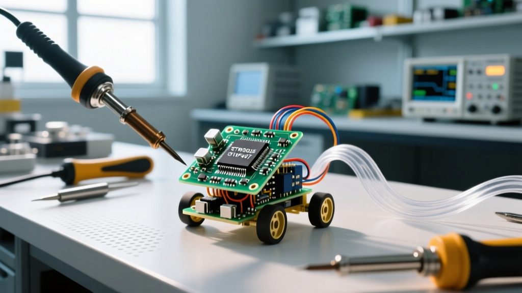

Microbots in real life are autonomous or semi-autonomous electromechanical systems under 100mm in scale that integrate microcontrollers, micro-actuators, and sensors to perform localized physical tasks. Building them fundamentally changes your circuit design approach: you abandon raw processing headroom in favor of extreme microwatt power-budget management, flexible PCB routing, and ultra-low-quiescent-current components. Hobbyists commonly confuse true embedded microbots with 'nanobots' (which are theoretical molecular-scale constructs) or standard micro-drones (which are essentially scaled-down RC toys lacking autonomous edge-compute and typically exceed 100mm in size).
Core Compute: Selecting the Brain for Sub-100mm Chassis
When you shrink a robot down to the size of a matchbox, the physical volume available for a battery drops cubically, but the energy required to run a standard microcontroller remains relatively fixed. This is where the embedded design diverges sharply from standard Arduino or Raspberry Pi projects. You cannot afford the 15mA to 50mA idle current draw of an ATmega328P or a full Raspberry Pi Zero. Instead, you must select System-on-Chip (SoC) architectures that offer deep sleep modes in the single-digit microamp range, integrated radio transceivers to eliminate external SPI Wi-Fi/BLE modules, and ultra-compact QFN (Quad Flat No-leads) packaging.
The table below compares the most viable microcontroller cores for microbot applications in 2026, focusing on the metrics that actually matter when your total battery capacity is under 150mAh.
| Microcontroller | Deep Sleep Current | Active Radio TX Current | Flash / SRAM | Typical Price (2026) |
|---|---|---|---|---|
| Microchip ATtiny85 | ~100 nA (Power-down) | N/A (No native radio) | 8 KB / 512 B | $1.20 |
| Espressif ESP32-C3 | ~5 µA (Deep Sleep) | ~80 mA (BLE 4.2 TX) | 400 KB / 400 KB | $1.50 |
| Nordic nRF52840 | ~1.5 µA (System OFF) | ~5 mA (BLE 5.0 TX) | 1 MB / 256 KB | $4.80 |
| Raspberry Pi RP2040 | ~1 mA (Dormant mode) | N/A (No native radio) | Ext. QSPI / 264 KB | $0.80 |
As detailed in the Espressif ESP32-C3 official documentation, the ESP32-C3 strikes a highly practical balance for hobbyist microbots. It provides enough SRAM to handle basic sensor fusion and motor control PID loops while maintaining a deep sleep current low enough to preserve micro-battery life. The nRF52840 is vastly superior for radio efficiency, but its higher cost and steeper learning curve (requiring the Zephyr RTOS or Nordic SDK) make it less accessible for rapid bench prototyping compared to the Arduino-compatible ESP32 ecosystem.
The Power Budget: A Worked Numeric Example
Let us run a concrete numeric example to illustrate the brutal reality of micro-scale power budgets. Assume we are building a 25mm soil-moisture sensing microbot powered by a standard 3.7V 100mAh lithium-polymer (LiPo) pouch cell. The total theoretical energy capacity is 370mWh.
The robot's operational loop is simple: wake from deep sleep, read an I2C capacitive soil moisture sensor, transmit the 12-byte payload via BLE to a central gateway, and return to sleep. The entire active sequence takes 50 milliseconds. The sleep interval between readings is 9.95 seconds, creating a neat 10-second duty cycle.
- Active Phase: 50ms at 80mA (ESP32-C3 BLE TX + sensor polling). Charge consumed = 80mA × 0.05s = 4.0 mAs.
- Sleep Phase: 9.95s at 5µA (0.005mA). Charge consumed = 0.005mA × 9.95s = 0.04975 mAs.
- Total Charge per Cycle: 4.04975 mAs.
Over one hour (360 cycles), the microbot consumes 1,457.91 mAs, which converts to approximately 0.405 mAh. Dividing our 100mAh battery capacity by the 0.405 mAh hourly draw yields a theoretical runtime of 246.9 hours (about 10.2 days).
The math above assumes an ideal battery. In reality, a 100mAh micro LiPo has a high Equivalent Series Resistance (ESR), often exceeding 2 ohms. When the ESP32-C3 ramps up its radio and pulls 80mA, Ohm's Law dictates a voltage sag of 160mV (0.08A × 2Ω) just from the cell. Combined with PCB trace resistance, the voltage at the MCU's VCC pin can easily drop below the 2.3V brownout threshold, causing a hard reset and an infinite boot-loop. The fix: You must place a low-ESR 100µF to 220µF MLCC (Multi-Layer Ceramic Capacitor) as close to the MCU's VCC pin as possible to supply the transient inrush current during the 50ms TX burst.
Where You Meet Microbots in Practice
Microbots in real life are not science fiction; they are actively deployed in specialized industrial and research environments where human access is impossible and larger robots lack the physical clearance. According to research highlighted by IEEE Spectrum's robotics division, the miniaturization of embedded compute has pushed these systems out of the lab and into the field.
1. Pipe Inspection and Conduit Crawlers
For inspecting pneumatic lines, HVAC conduits, or residential plumbing under 50mm in diameter, engineers use magnetic-tracked microbots. These rely on coreless DC micro-gearmotors (like the 6mm Nidec or Pololu micro metal gearmotors) driven by ultra-compact H-bridges such as the TI DRV8837. The embedded controller uses IMU data to maintain wall-pressurization while streaming low-bandwidth telemetry back to the surface.
2. Precision Agriculture Swarm Sensing
Instead of using a single large rover to map soil acidity across a farm, researchers deploy 'smart dust' style microbots. These 30mm nodes use piezoelectric actuators or shape-memory alloy (SMA) wires to inch through topsoil. Because SMA wires draw high current but only for milliseconds, the embedded firmware must precisely time the PWM pulses to prevent draining the micro-battery, relying heavily on the deep-sleep capabilities discussed earlier.
3. Structural Health Monitoring
Microbots equipped with ultrasonic transducers crawl along the internal welds of aerospace fuel tanks or bridge supports. In these installations, the 'circuit' changes dramatically: standard rigid FR4 PCBs are replaced by flexible polyimide PCBs (flex circuits) that wrap around the curved chassis of the robot, and 0201 or 01005 surface-mount passives are mandatory to save square millimeters of board space.
Debugging and Edge Cases in Micro-Scale Embedded Design
When you bring a microbot to the bench for debugging, standard practices often fail due to the physical scale of the hardware. Here are the most common edge cases and how to resolve them.
Why does my BLE range drop to less than 2 meters on my microbot?
At sub-100mm scales, you rarely have room for a dedicated ceramic chip antenna or a proper PCB trace antenna with the required ground plane keepout. If your ground plane is smaller than 20mm x 20mm, the antenna efficiency plummets. Fix: Use a wire antenna (a 31mm quarter-wave whip for 2.4GHz) routed vertically away from the chassis, or switch to a sub-GHz radio (like an 868/915 MHz LoRa module) where the longer wavelength is more forgiving of compromised ground planes, albeit at the cost of higher active current.
My micro-motors cause the I2C sensor readings to corrupt. How do I isolate them?
Brushed coreless DC motors generate massive electromagnetic interference (EMI) and voltage spikes on the power rails when the commutator switches. On a microbot, the motor power traces often run millimeters away from the I2C SDA/SCL lines. Fix: Solder 100nF ceramic capacitors directly across the motor terminals at the motor casing itself, not on the PCB. Additionally, add 4.7kΩ pull-up resistors to the I2C lines and route them on the opposite layer of your flex PCB from the motor power traces.
How do I safely charge a microbot without adding bulky USB-C ports?
Adding a USB-C port and a full charge management IC wastes precious volume. Instead, use exposed gold pogo-pin pads on the microbot's chassis that mate with a magnetic charging dock. Use a highly integrated, ultra-small charger IC like the TI BQ24040 in a 2x2mm SON package on the docking station side, keeping the microbot's internal circuitry completely free of charging logic. Always ensure your docking station includes a hardware temperature thermistor loop to prevent thermal runaway in the tiny LiPo cell.
Designing microbots in real life requires a fundamental shift from 'making it work' to 'making it survive the physics of its own scale'. By respecting the strict power budgets, managing transient current sags with strategic decoupling, and selecting the right low-power SoC, you can build autonomous embedded systems that punch far above their physical weight class.


