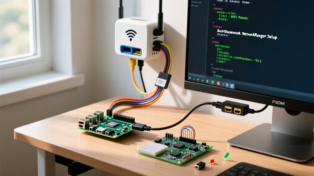
Project Overview: Native USB HID Macro Controller
When evaluating ESP32-S3 projects for human interface devices (HID), the defining advantage over the classic ESP32 is the native USB OTG peripheral. You no longer need an external bridge chip like an ATmega32U4 or a CH340 to emulate a keyboard or MIDI controller. The ESP32-S3 speaks directly to the host OS via its D+ and D- pins.
This guide walks through building a 4-key macro pad with a rotary encoder and an OLED status screen. We will use the ESP32 Arduino Core v3.x, which natively integrates Adafruit's TinyUSB stack, eliminating the fragile legacy USB libraries that plagued early S3 development.
Hardware Spec Sheet & Pin Mapping
Before wiring, verify your exact module variant. The S3 has 45 programmable GPIOs, but many are consumed by internal PSRAM/Flash routing. The pinout below avoids all strapping pins and internal SPI bus conflicts.
| Component | Exact Part / Variant | ESP32-S3 GPIO | Notes & Constraints |
|---|---|---|---|
| Microcontroller | ESP32-S3-DevKitC-1 (N8R2) | N/A | Ensure header pins are soldered; factory units often ship unpopulated. |
| OLED Display | 0.96" SSD1306 I2C (128x64) | SDA: GPIO 8 SCL: GPIO 9 |
Use 4.7kΩ pull-up resistors on SDA/SCL if the display module lacks them. |
| Rotary Encoder | EC11 with breakout board | DT: GPIO 38 CLK: GPIO 39 SW: GPIO 40 |
Encoder breakout must include hardware debounce capacitors (usually 0.1µF). |
| Macro Switch 1 | Cherry MX / Kailh socket | GPIO 1 | Wire to GND. Use internal pull-up. |
| Macro Switch 2 | Cherry MX / Kailh socket | GPIO 2 | Wire to GND. Use internal pull-up. |
| Macro Switch 3 | Cherry MX / Kailh socket | GPIO 4 | Wire to GND. Note: GPIO4 is a strapping pin; pull high for normal boot. |
| Macro Switch 4 | Cherry MX / Kailh socket | GPIO 5 | Wire to GND. Use internal pull-up. |
Step-by-Step Assembly & Compilable Code
- Prepare the I2C Bus: Connect the SSD1306 VCC to the DevKit's 3V3 pin (do not use 5V, the S3 GPIOs are strictly 3.3V tolerant and the onboard regulator handles the step-down). Connect SDA to GPIO 8 and SCL to GPIO 9.
- Wire the Switches: Connect one leg of each mechanical switch to GND, and the other leg to their respective GPIOs (1, 2, 4, 5). We will enable internal pull-ups in software to save on physical resistors.
- Install Core Libraries: In the Arduino IDE Board Manager, install
esp32 by Espressif Systemsversion 3.0.0 or higher. In the Library Manager, installAdafruit SSD1306andAdafruit GFX Library. - Configure Board Settings: Under Tools, set Board to "ESP32S3 Dev Module". Crucially, set USB CDC On Boot to "Enabled", and USB Mode to "Hardware CDC and JTAG". This ensures the TinyUSB stack initializes correctly for HID.
Below is the complete, compilable Arduino code. It initializes the TinyUSB HID keyboard stack, maps the switches to specific keystrokes (Ctrl+C, Ctrl+V, Enter, Escape), and updates the OLED with the last pressed key.
#include <Wire.h>
#include <Adafruit_GFX.h>
#include <Adafruit_SSD1306.h>
#include <USB.h>
#include <USBHIDKeyboard.h>

// --- Pin Definitions ---
#define PIN_SW1 1
#define PIN_SW2 2
#define PIN_SW3 4
#define PIN_SW4 5
#define PIN_ENC_DT 38
#define PIN_ENC_CLK 39

// --- Display Setup ---
#define SCREEN_WIDTH 128
#define SCREEN_HEIGHT 64
#define OLED_RESET -1
#define SCREEN_ADDRESS 0x3C
Adafruit_SSD1306 display(SCREEN_WIDTH, SCREEN_HEIGHT, &Wire, OLED_RESET);

// --- USB HID Setup ---
USBHIDKeyboard Keyboard;

// --- Debounce Variables ---
const int switchPins[4] = {PIN_SW1, PIN_SW2, PIN_SW3, PIN_SW4};
bool lastSwState[4] = {HIGH, HIGH, HIGH, HIGH};
unsigned long lastDebounceTime[4] = {0, 0, 0, 0};
const unsigned long debounceDelay = 50;

void setup() {
  // Initialize Switches with internal pull-ups
  for (int i = 0; i < 4; i++) {
    pinMode(switchPins[i], INPUT_PULLUP);
  }

  pinMode(PIN_ENC_DT, INPUT_PULLUP);
  pinMode(PIN_ENC_CLK, INPUT_PULLUP);

  // Initialize OLED with error handling
  if(!display.begin(SSD1306_SWITCHCAPVCC, SCREEN_ADDRESS)) {
    // Halt execution if display fails to initialize to prevent I2C bus lockups
    for(;;);
  }

  display.clearDisplay();
  display.setTextSize(1);
  display.setTextColor(SSD1306_WHITE);
  display.setCursor(0,0);
  display.println("ESP32-S3 HID");
  display.println("Initializing...");
  display.display();

  // Initialize USB Stack
  USB.begin();
  Keyboard.begin();

  delay(500); // Allow host OS to enumerate USB device

  display.clearDisplay();
  display.setCursor(0,0);
  display.println("Ready.");
  display.display();
}

void loop() {
  // Handle Macro Switches
  for (int i = 0; i < 4; i++) {
    int reading = digitalRead(switchPins[i]);
    if (reading != lastSwState[i]) {
      lastDebounceTime[i] = millis();
    }

    if ((millis() - lastDebounceTime[i]) > debounceDelay) {
      if (reading == LOW) { // Switch pressed (pulled to GND)
        triggerMacro(i);
      }
    }
    lastSwState[i] = reading;
  }
}

void triggerMacro(int index) {
  display.clearDisplay();
  display.setCursor(0, 0);

  switch(index) {
    case 0:
      Keyboard.press(KEY_LEFT_CTRL);
      Keyboard.press('c');
      Keyboard.releaseAll();
      display.println("Macro 1: Copy");
      break;
    case 1:
      Keyboard.press(KEY_LEFT_CTRL);
      Keyboard.press('v');
      Keyboard.releaseAll();
      display.println("Macro 2: Paste");
      break;
    case 2:
      Keyboard.press(KEY_RETURN);
      Keyboard.releaseAll();
      display.println("Macro 3: Enter");
      break;
    case 3:
      Keyboard.press(KEY_ESC);
      Keyboard.releaseAll();
      display.println("Macro 4: Escape");
      break;
  }
  display.display();
}
Debugging: "Timed out waiting for packet header"
The most frequent failure mode when flashing ESP32-S3 projects via the Arduino IDE is the board refusing to enter download mode. Because the S3 uses native USB for both serial output and JTAG debugging, a misconfiguration in the boot strapping pins will cause the host PC to lose the serial connection right when the IDE attempts to upload.
The Exact Error String:
A fatal error occurred: Failed to connect to ESP32-S3: Timed out waiting for packet header.
Ranked Causes:
- Stuck in USB-JTAG Mode: GPIO 3 is pulled low during boot, forcing the chip into USB peripheral mode rather than UART/SPI download mode. The Arduino IDE's auto-reset circuit cannot override this hardware strapping.
- Charge-Only USB-C Cable: The ESP32-S3-DevKitC-1 ships with a USB-C port wired directly to the native D+/D- pins. If your cable lacks data lines, the PC will supply 5V power, but the TinyUSB stack cannot enumerate, resulting in no COM port.
- Missing CDC Drivers on Windows: While Windows 10/11 usually handles CDC natively, some enterprise LTSC builds lack the
usbser.sysdriver mapping for the Espressif VID/PID combo, causing the device to show up as "Unknown USB Device" rather than a COM port.
The First Three Things to Check When It Fails:
- Manual Boot Override: Press and hold the
BOOTbutton on the DevKit. While holding it, press and release theRESETbutton, then releaseBOOT. This forces GPIO 0 low during the reset cycle, manually triggering the ROM serial bootloader. Click "Upload" in the IDE immediately after. - Verify Cable Integrity: Swap your USB-C cable for one you have personally verified transfers data (e.g., one that works with a smartphone file transfer). Bend the cable near the connector; cheap micro-USB-to-USB-C adapters often break the D+ trace internally.
- Check Device Manager Enumeration: Open Windows Device Manager. If you see "USB JTAG/serial debug unit" under Universal Serial Bus devices, but no COM port under Ports (COM & LPT), your Arduino Core is outdated. Update to v3.0.0+ which properly maps the CDC interface.
Extending and Simplifying the Build
Depending on your enclosure constraints and power budget, you can scale this project in either direction.
How to Simplify: If you are building a low-profile macro pad for a laptop bag, drop the SSD1306 OLED entirely. The I2C bus initialization adds roughly 120ms to the boot time and draws an continuous 8mA. By removing the display and relying purely on the HID output, the S3 can be put into light sleep between keypresses, reducing idle current from ~45mA to under 2mA, making it viable to run off a 200mAh LiPo cell for weeks.
How to Extend: The ESP32-S3's USB stack supports composite devices. You can extend this build by adding USBHIDMIDI.h alongside the keyboard library. This allows Switch 1 to act as a keyboard macro for your IDE, while Switch 2 sends a MIDI Note On/Off message to Ableton Live. Additionally, wire a strip of WS2812B LEDs to GPIO 48 (the default onboard RGB LED pin on the DevKitC-1) to provide per-key RGB feedback without consuming extra GPIOs.
ESP32-S3 Projects FAQ
What makes the ESP32-S3 better than the classic ESP32 for USB projects?
The classic ESP32 lacks native USB hardware; it relies on a secondary chip (like a CP2102 or CH340) for serial communication and cannot natively emulate a keyboard or mouse without complex software workarounds over Bluetooth. The ESP32-S3 features a dedicated USB 1.1 Full-Speed OTG controller. This allows it to appear as a native HID device over a physical cable with sub-millisecond latency, completely bypassing the Bluetooth stack and its inherent pairing delays and bandwidth limits.
Can I run camera projects alongside USB HID on the ESP32-S3?
Yes, but with memory caveats. The ESP32-S3 includes a dedicated LCD/Camera interface (DVP) and AI vector instructions that accelerate image processing. However, streaming a 2MP OV2640 camera while simultaneously maintaining a TinyUSB HID stack requires significant RAM. You must use a variant with at least 8MB of PSRAM (like the N8R8) to buffer the camera frames via DMA while the CPU handles the USB interrupt service routines. If you use an N8R2 (2MB PSRAM), you will likely encounter Guru Meditation Error: Core 1 panic'ed (Interrupt wdt timeout) under heavy USB polling.
Why does my ESP32-S3 project drain battery in deep sleep?
The most common culprit in S3 deep sleep current leaks is the native USB peripheral and the I2C bus. Before calling esp_deep_sleep_start(), you must explicitly power down the USB PHY and set the I2C pins (SDA/SCL) to high-impedance inputs. If you leave the I2C pins configured as outputs, the SSD1306 display will backfeed power through its internal protection diodes, drawing 3-5mA even when the display is "off". Furthermore, ensure USB CDC is disabled in the board settings for battery-operated deployments, as the S3 will periodically wake the USB PHY to check for host connection, ruining the micro-amp sleep profile.