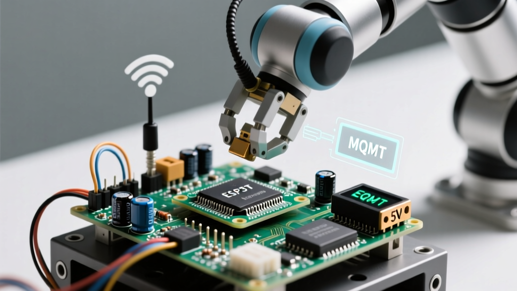

When building a robotic arm for home automation or remote industrial monitoring, tethering it to a physical joystick limits its utility. By integrating an ESP32 and leveraging the MQTT protocol, you transform a standard 4-DOF (Degree of Freedom) manipulator into a low-latency, IoT-connected device capable of receiving telemetry and executing spatial commands from anywhere in the world.
The Architecture of an IoT-Connected Manipulator
Unlike standard RC-controlled arms that rely on direct PWM signals from a potentiometer, an IoT robotic arm decouples the physical interface from the actuator array. The ESP32 acts as an edge node, subscribing to MQTT topics for joint angles while simultaneously publishing telemetry (like current draw and gripper limit-switch states) back to a cloud dashboard like Node-RED or AWS IoT Core.
Engineer's Note: The primary bottleneck in IoT robotics isn't processing power; it's network latency and power rail stability. A 200ms WiFi ping is acceptable for a weather station, but it causes dangerous overshoot in a robotic arm holding a fragile payload. Local MQTT brokers (like Mosquitto on a Raspberry Pi) are mandatory for sub-20ms actuation loops.
Actuator Selection: Torque, Backlash, and Digital Protocols
The most common mistake when building a robotic arm is underestimating the static torque required to hold the arm extended. The horizontal reach multiplies the gravitational load on the base and shoulder servos.
| Servo Model | Stall Torque (6V) | Control Type | Best Application | Approx. Cost |
|---|---|---|---|---|
| TowerPro MG996R | 13 kg-cm | Analog PWM | Base rotation (Yaw) | $6.50 |
| DS3218 20KG | 20 kg-cm | Digital PWM | Shoulder/Elbow (Pitch) | $14.00 |
| MG90S (Metal) | 2.2 kg-cm | Analog PWM | Wrist/Gripper | $4.00 |
For the shoulder and elbow joints, the DS3218 digital servo is highly recommended over the ubiquitous MG996R. Digital servos utilize an internal microcontroller to sample the potentiometer and drive the motor at higher frequencies, resulting in a much stiffer 'dead band' and superior holding torque. When building a robotic arm meant to lift 500g payloads at a 30cm reach, the analog MG996R will sag and chatter under load.
The Power Delivery Trap: Preventing ESP32 Brownouts
Servos are inductive loads. When a DS3218 stalls or rapidly changes direction, it can pull upwards of 2.5 Amps momentarily. If you power the ESP32 and the servos from the same 5V USB buck converter, the voltage will dip below 4.2V, triggering the ESP32's brownout detector (BOD) and causing an immediate reboot.
The Solution: Use a dedicated 5V 10A switching power supply, such as the Mean Well LRS-50-5. Wire the servo power rail directly to this supply, and use a separate high-efficiency buck converter (like the LM2596 set to 5V) or the ESP32's onboard AMS1117 regulator for the microcontroller. Crucially, solder a 1000µF electrolytic capacitor and a 0.1µF ceramic capacitor in parallel across the main servo power terminals to absorb inductive spikes.
ESP32 PWM Mapping and the LEDC API
With the transition to ESP32 Arduino Core v3.x, the legacy analogWrite() function has been deprecated for servo control. You must use the LEDC (LED Control) peripheral, which provides hardware-backed PWM resolution.
According to the official Espressif LEDC API documentation, standard servos require a 50Hz signal (20ms period). A pulse width of 1000µs represents 0°, and 2000µs represents 180°.
// ESP32 LEDC Servo Setup Snippet
#define SERVO_FREQ 50
#define RESOLUTION 16
ledcSetup(0, SERVO_FREQ, RESOLUTION);
ledcAttachPin(13, 0); // GPIO 13 for Shoulder Servo
// Map 0-180 degrees to 1000-2000us pulse width
uint32_t duty = map(angle, 0, 180, 3276, 6553);
ledcWrite(0, duty);
Designing the MQTT Payload for Kinematics
Sending raw integer values (e.g., '90') over MQTT is a poor practice for IoT devices. It lacks context and error-checking. Instead, structure your telemetry and command payloads using JSON.
Following the MQTT v5 specification, utilizing QoS 1 (At least once delivery) ensures that critical joint commands aren't dropped over unstable WiFi networks, though you must implement message deduplication on the ESP32.
Command Payload Structure
{
  "arm_id": "flux_arm_01",
  "timestamp": 1698745200,
  "joints": {
    "base": 90,
    "shoulder": 45,
    "elbow": 120,
    "gripper": 0
  },
  "velocity_profile": "ease_in_out"
}
By including a velocity_profile key, the ESP32 firmware can interpolate the movement using a trapezoidal or S-curve algorithm, preventing the violent jerks that strip 3D-printed gears and destabilize the arm's base.
Inverse Kinematics (IK) vs. Direct Joint Control
When building a robotic arm for IoT applications, you must decide where the Inverse Kinematics (IK) calculations occur. IK is the mathematical process of translating a desired 3D Cartesian coordinate (X, Y, Z) into the specific joint angles required to reach that point.
Edge Computing vs. Cloud Computing
Running the IK solver directly on the ESP32 is possible using libraries like FABRIK or standard Denavit-Hartenberg parameters, but it consumes significant CPU cycles and can cause WiFi stack starvation if not pinned to Core 0 (while WiFi runs on Core 1). Alternatively, you can offload the IK calculations to a Raspberry Pi or cloud server. The cloud server calculates the joint angles and sends the resulting JSON payload over MQTT to the ESP32, which simply acts as a dumb PWM translator. This edge-cloud hybrid approach is highly recommended for complex 6-DOF arms where floating-point math might introduce latency.
Mechanical Assembly and Backlash Mitigation
When building a robotic arm from 3D-printed parts (PETG or ABS), the Z-axis layer adhesion becomes a critical failure point under torsional load. Do not use PLA; it suffers from cold creep and will permanently deform if the arm is left extended for several hours.
- Harmonic Vibration: Mount the ESP32 and the IMU (like an MPU6050 used for closed-loop feedback) on a TPU (flexible filament) isolation pad. The high-frequency vibration from digital servos will otherwise induce noise into the IMU's accelerometer, causing the PID loop to overcorrect.
- Counterweighting: Add a physical counterweight to the rear of the base joint. This reduces the continuous current draw on the base servo by up to 40%, drastically extending the lifespan of the internal brass bushings.
- Cable Management: Route servo wires through the center axis of rotation where possible. Exposed cables wrapping around the elbow joint will eventually fatigue and snap internally, leading to a loss of PWM signal and a catastrophic arm drop.
Troubleshooting IoT Latency and Servo Jitter
If your robotic arm exhibits 'jitter' (micro-oscillations of 1-2 degrees), diagnose the root cause before altering your software.
- Electrical Noise: Check your 5V rail with an oscilloscope. If you see >100mV of ripple, your power supply is failing to filter the AC switching noise, or your ground wires are too thin (use at least 18 AWG for the main servo ground).
- WiFi Interference: The ESP32 operates on the 2.4GHz band, sharing frequencies with Bluetooth and household microwaves. Bind your ESP32 to a dedicated 2.4GHz IoT VLAN on your router, and force it to use WiFi Channel 1, 6, or 11 to avoid overlapping interference.
- Potentiometer Wear: Analog servos use physical carbon-track potentiometers for position feedback. Over time, the wiper creates dead spots. If jitter only occurs at specific angles, the servo is mechanically degraded and must be replaced or upgraded to a magnetic hall-effect servo.
Building an IoT-connected robotic arm bridges the gap between software kinematics and harsh electromechanical realities. By prioritizing robust power delivery, utilizing the ESP32's hardware LEDC timers, and structuring your MQTT payloads for deterministic execution, you will create a manipulator that is as reliable on a factory floor as it is in a home automation lab.