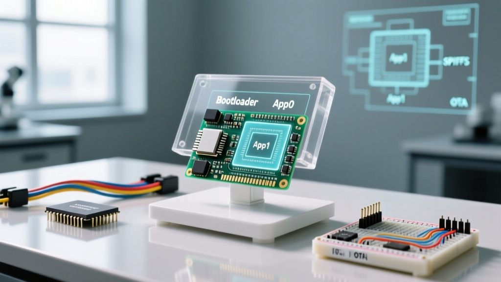

Setting up an ESP32's flash environment means defining the partition table that dictates how the chip's external SPI flash memory is divided between the bootloader, application firmware, OTA updates, and non-volatile storage (NVS). When you click "Upload" in the Arduino IDE, you aren't just sending your C++ code to the board; you are writing a highly specific binary map to the silicon. Understanding this map is the difference between a robust, field-updatable IoT device and a bricked board that requires a physical USB cable to recover.
This setup changes three critical things in your installation: it dictates the absolute maximum size of your compiled sketch, determines whether Over-The-Air (OTA) updates are physically possible, and allocates dedicated sectors for persistent key-value data or filesystem storage. The most common mistake I see on the workbench is makers confusing the ESP32's internal 520KB SRAM (where variables live while the code is running) with the 4MB to 16MB external SPI flash (where the code and files are stored while powered off). Furthermore, many assume the partition table is compiled into the sketch binary, rather than being flashed as a separate CSV-compiled binary at a hardcoded memory offset.
The Anatomy of an ESP32 Partition Table
Think of the ESP32's SPI flash like a physical filing cabinet. The bootloader is the lock on the front door, the partition table is the index card drawer telling you which files are in which folders, and the app/filesystem partitions are the actual folders. The ESP32 ROM bootloader always looks for the partition table at a hardcoded hex offset of 0x8000. If it doesn't find a valid table there, the chip halts.
Let's look at a worked numeric example using a standard 4MB ESP32-WROOM-32 module configured for OTA updates. Here is the exact hex math that the Espressif toolchain uses to slice up the 4,194,304 bytes of flash:
| Partition Name | Type | Offset (Hex) | Size (Hex / Decimal) | Purpose |
|---|---|---|---|---|
| nvs | data | 0x9000 | 0x5000 (20KB) | Wi-Fi credentials, preferences |
| otadata | data | 0xe000 | 0x2000 (8KB) | Tracks which OTA app slot is active |
| app0 (ota_0) | app | 0x10000 | 0x140000 (1.25MB) | Primary firmware binary |
| app1 (ota_1) | app | 0x150000 | 0x140000 (1.25MB) | Staging area for new OTA firmware |
| spiffs / littlefs | data | 0x290000 | 0x170000 (1.43MB) | Web server files, logs, assets |
app0 (0x10000) plus its size (0x140000) equals exactly the start of app1 (0x150000). The start of app1 (0x150000) plus its size (0x140000) equals the start of the filesystem (0x290000). Add the filesystem size (0x170000), and you hit exactly 0x400000 — which is 4MB in hexadecimal. No wasted bytes, no overlaps.
According to the official Espressif Partition Tables documentation, app partitions must be aligned to 0x10000 (64KB) boundaries. If you try to manually shrink app0 to 1.1MB to give more room to your filesystem, the compiler will throw an alignment error because 1.1MB doesn't map cleanly to the required 64KB flash erase sectors.
Where You Meet This in Practice
You typically interact with this theory in the Arduino IDE via the Tools > Partition Scheme dropdown. When you select "Default 4MB with spiffs (1.2MB APP/1.5MB SPIFFS)", the IDE simply passes a pre-written CSV file to the esptool.py uploader.
However, you meet the consequences of this setup in three specific scenarios:
- The "Sketch Too Big" Error: Your code compiles to 1.3MB, but your selected partition scheme only allocated 1.25MB for
app0. The linker fails. The fix isn't always to optimize your code; often, it's to switch to a "No OTA (2MB APP/2MB SPIFFS)" scheme if you don't actually need wireless updates. - OTA Rollbacks: If an OTA update loses power halfway through writing to
app1, the ESP32 boot sequence (detailed in the Espressif Startup Guide) checks theotadatapartition, realizesapp1is marked invalid, and automatically boots back into the oldapp0firmware. This fail-safe only works if your partition setup actually includes anotadatasector. - NVS Corruption: If you store Wi-Fi passwords using the
Preferenceslibrary, it writes to thenvspartition. If you flash a new firmware via USB and forget to check "Erase All Flash Before Sketch Upload", the old NVS data persists. If your new code expects different data types in those keys, the ESP32 will throw a Guru Meditation Error on boot.
Real-World Scenario Walkthrough: The OTA Brick
Let's walk through a bench failure that perfectly illustrates why treating the ESP32 setup as a black box leads to disaster.
The Setup: The developer realizes the default OTA scheme only leaves 1.43MB for the filesystem, but their web assets total 1.8MB. To fix this, they select the "No OTA (2MB APP/2MB SPIFFS)" partition scheme in the Arduino IDE to get the space they need. However, they leave the ArduinoOTA.begin() initialization code in their setup() loop, assuming the library will just "figure it out" or gracefully disable itself.
The Numbers: In the "No OTA" scheme, the flash is split into a single 2MB app0 partition and a 2MB filesystem. There is no app1 partition, and critically, there is no otadata partition. The total flash is fully accounted for without OTA staging areas.
The Outcome: The code compiles successfully. The developer uploads it via USB. The thermostat boots, the web server loads the 1.8MB assets perfectly from LittleFS, and the device connects to Wi-Fi. The developer decides to test an OTA update by pushing a minor code tweak over the network.
What Went Wrong: The ArduinoOTA library attempts to open the ota_1 partition to begin writing the new binary. Because the partition table flashed to 0x8000 doesn't contain an ota_1 definition, the flash write operation defaults to an invalid memory address or overwrites the adjacent LittleFS partition. The update appears to finish, the ESP32 reboots, and immediately enters a bootloop. The serial monitor spits out: Guru Meditation Error: Core 1 panic'ed (Cache disabled but cached memory region accessed). The device is bricked and requires a physical USB connection to re-flash.
The Fix: You cannot have a 2MB filesystem and OTA on a 4MB chip. The math doesn't lie. The developer had to either compress the web assets to fit under 1.43MB, upgrade to an ESP32-S3 with 8MB or 16MB of flash, or abandon OTA updates entirely and remove the library from the code.
Frequently Asked Questions
Can I change the partition table without erasing my NVS data?
Yes, but with extreme caution. If you upload a new sketch via USB, the Arduino IDE typically only overwrites the app0 partition and the partition table itself. However, if your new partition table shifts the hex offset of the nvs partition, your old data will be misaligned and read as corrupt. Always back up NVS data to the cloud or SD card before changing partition schemes in production.
Why does my 16MB ESP32 only show 4MB of available flash?
The physical silicon on your ESP32-WROOM or ESP32-S3 module might have 16MB of flash, but the Arduino IDE defaults to a 4MB partition map unless you explicitly change it. Go to Tools > Flash Size and select "16MB (128Mb)", then choose a partition scheme designed for 16MB (like "16M Flash (3MB APP/9.9MB FAT)"). The hardware can only use what the partition table defines.
What is the difference between SPIFFS and LittleFS in the partition table?
In the partition table CSV, both use the data type, but SPIFFS uses the spiffs subtype, while LittleFS uses the spiffs subtype as well (for legacy Arduino core compatibility) or littlefs in newer ESP-IDF implementations. LittleFS is vastly superior for power-loss resilience and wear leveling. As of 2026, SPIFFS is effectively deprecated; always format your data partitions as LittleFS in your code, even if the CSV subtype says spiffs.


