
Why the ESP32 Dominates Modern Robotics Projects
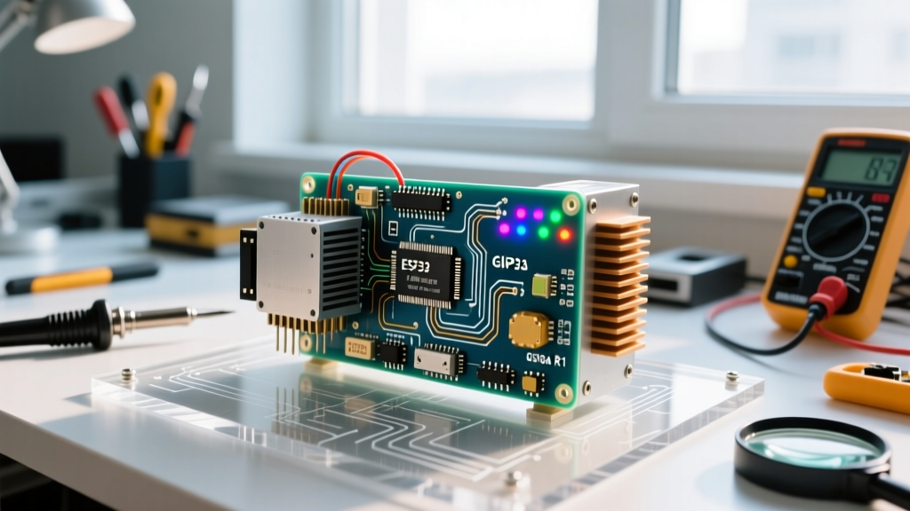
When engineers and makers evaluate components for advanced robotics projects, the transition from 8-bit microcontrollers to 32-bit architectures is no longer optional. The ESP32 DevKit V1 has become the undisputed champion for autonomous rovers, line-followers, and robotic arms. Unlike legacy 8-bit boards that struggle with floating-point math and multitasking, the ESP32 features a dual-core 32-bit LX6 microprocessor running at 240MHz. This allows you to dedicate Core 0 to real-time PID motor control and sensor polling, while Core 1 handles WiFi telemetry, ROS (Robot Operating System) communication, or over-the-air (OTA) firmware updates. According to the Espressif ESP32 Official Documentation, the chip also boasts a 12-bit ADC (Analog-to-Digital Converter), which is critical for reading precise analog values from infrared reflectance sensors without external multiplexers.
Bill of Materials: Sourcing the Right Hardware
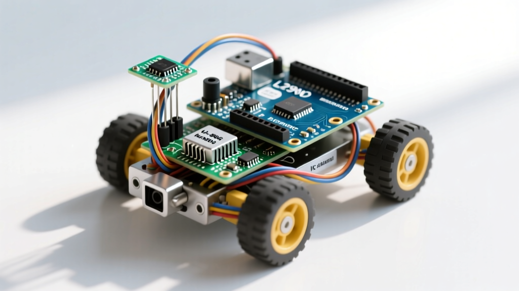
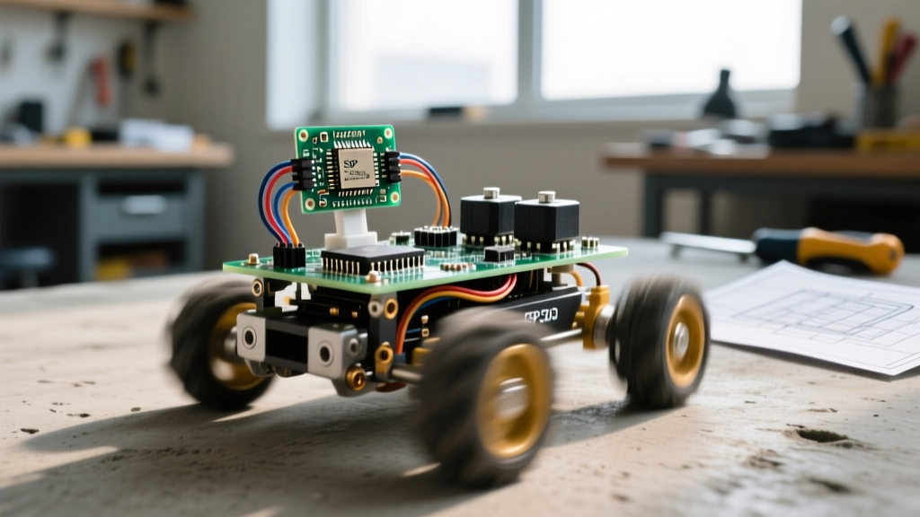
Successful robotics projects rely on matching the right mechanical components with compatible electronics. Below is the exact Bill of Materials (BOM) used for this 2WD autonomous line-following rover build.
| Component | Specification | Est. Price | Engineering Notes |
|---|---|---|---|
| Microcontroller | ESP32 DevKit V1 (30-pin) | $6.00 | Ensure you get the 30-pin version for breadboard compatibility. |
| Motor Driver | L298N Dual H-Bridge | $4.50 | High voltage drop (~2V). Requires higher voltage battery pack. |
| Drive Motors | N20 6V 100RPM Gear Motors (x2) | $9.00 | 100RPM provides the ideal balance of torque and speed for PID tuning. |
| IR Sensors | TCRT5000 Reflective Optical (x3) | $3.50 | Must use analog output pins for proportional line tracking. |
| Power Source | 2S 7.4V 1000mAh LiPo | $14.00 | Provides necessary voltage overhead for the L298N BJT drop. |
| Chassis | Custom 3D Printed PLA / Acrylic | $10.00 | Low center of gravity is critical to prevent tipping on sharp turns. |
| Wheels | 42mm N20 Compatible Rubber Wheels | $5.00 | Rubber tires provide higher static friction than plastic alternatives. |
Chassis Assembly and Mechanical Drivetrain
The mechanical foundation of any robotics project dictates how well your software can perform. If your chassis flexes or your wheels slip, even a perfectly tuned PID algorithm will fail. Begin by mounting the N20 gear motors to the 3D-printed chassis using M3 screws and brass threaded inserts. Avoid using hot glue for motor mounts; the heat generated by the motors during stall conditions can soften the glue, leading to misaligned drivetrains.
Mounting the N20 Gear Motors and Castor
Position the drive wheels slightly behind the robot's center of mass. This shifts the weight onto the front castor wheel, reducing the normal force on the drive wheels just enough to allow for aggressive, tight-radius pivoting without stalling the motors. Use a 15mm steel ball castor rather than a plastic omnidirectional wheel. Steel ball castors have significantly lower rolling resistance on smooth surfaces, which reduces the baseline current draw from your LiPo battery.
Wiring the L298N Motor Driver and Power Distribution
Power distribution is where most intermediate robotics projects fail. The L298N motor driver uses Bipolar Junction Transistors (BJTs) in its H-bridge configuration. As detailed in the STMicroelectronics L298N Datasheet, this topology introduces a saturation voltage drop of approximately 1.8V to 2.0V. If you power the board with a standard 4xAA NiMH battery pack (nominally 4.8V), your motors will only receive 2.8V, resulting in sluggish movement and insufficient torque.
To solve this, we use a 2S LiPo battery (7.4V nominal, 8.4V fully charged). After the 2V drop across the L298N, the N20 motors receive roughly 5.4V to 6.4V, which is perfectly within their optimal operating range.
- Connect the 2S LiPo positive (red) wire to the L298N 12V terminal.
- Connect the LiPo negative (black) wire to the L298N GND terminal.
- Critical Step: Run a jumper wire from the L298N GND to one of the ESP32 GND pins. A common ground is mandatory for the ESP32's PWM logic signals to be recognized by the motor driver.
- Connect ESP32 GPIO 27 and GPIO 26 to L298N IN1 and IN2 (Left Motor).
- Connect ESP32 GPIO 25 and GPIO 33 to L298N IN3 and IN4 (Right Motor).
- Connect ESP32 GPIO 14 and GPIO 12 to L298N ENA and ENB (PWM Speed Control).
Integrating TCRT5000 IR Sensors for Line Tracking
For precise line tracking, digital outputs are insufficient because they only tell you if the sensor is on or off the line. By utilizing the analog output (AO) pin of the TCRT5000 sensor, the ESP32 can measure the exact gradient of reflectance, allowing the robot to 'see' the edge of the line and steer proportionally.
Wire the VCC and GND of the three TCRT5000 sensors to the ESP32's 3.3V and GND rails. Connect the AO pins to ESP32 GPIO 34 (Left), GPIO 35 (Center), and GPIO 36 (Right). Note that GPIOs 34, 35, and 36 are input-only pins on the ESP32 and lack internal pull-up/pull-down resistors. However, the TCRT5000's op-amp output drives the line actively, so floating pin issues are mitigated. When configuring the ESP32 ADC in your firmware, you must set the attenuation to ADC_ATTEN_DB_11 to allow for the full 0-3.3V input range, yielding a 12-bit resolution (0-4095).
Firmware Development: PID Control Logic
The core of autonomous robotics projects lies in the control loop. A simple bang-bang controller (turn left if off-line, turn right if on-line) results in a jerky, oscillating path. Instead, we implement a Proportional-Integral-Derivative (PID) controller. For line following, the Proportional (P) and Derivative (D) terms are usually sufficient; the Integral (I) term is often omitted to prevent wind-up on long curves.
The error is calculated by weighting the sensor inputs. For example, if the left sensor reads high reflectance (white) and the right reads low (black), the robot is drifting left. The firmware assigns positional weights to the sensors (e.g., Left = -10, Center = 0, Right = 10). The error is the sum of (SensorValue * Weight).
Calibrating the Base Speed and Kp Values
Tuning the Kp (Proportional gain) value requires iterative testing. Start with a Base Speed of 150 (out of 255 PWM) and a Kp of 10. If the robot oscillates wildly across the line, your Kp is too high. If the robot drifts off the line on sharp corners, your Kp is too low or your Base Speed is too high. Implement a low-pass filter in your code to smooth out the ADC noise from the TCRT5000 sensors, which can otherwise cause high-frequency motor jitter.
Pro-Tip: LiPo batteries suffer from voltage sag under heavy acceleration. Always implement a software-based low-voltage cutoff in your ESP32 code. If the analog reading of the battery voltage divider drops below 6.4V (3.2V per cell), halt the motors immediately to prevent permanent chemical damage to the LiPo cells.
Troubleshooting Common Robot Drift and Jitter
Even with perfect wiring, robotics projects often suffer from high-frequency jitter or unexplained drift. Here is a diagnostic framework for the most common ESP32 rover issues:
- Motor Whine and Heat: The ESP32's default PWM frequency is 5000Hz (5kHz). The L298N is an older, slower BJT-based driver. Switching at 5kHz causes massive switching losses and heat generation in the L298N. Use the ESP32 LEDC API to lower the PWM frequency to 1000Hz (1kHz). This eliminates the audible whine and reduces driver heat, as recommended when comparing legacy drivers to modern MOSFET alternatives like the Texas Instruments DRV8833.
- ADC Non-Linearity: The ESP32's ADC is notoriously non-linear at the extreme ends (near 0 and near 4095). Calibrate your TCRT5000 sensors so that the 'black' reading sits around 500 and the 'white' reading sits around 3500, avoiding the hardware dead-zones.
- Ground Loops: If the ESP32 resets randomly when the motors engage, you have a ground loop or voltage brownout. Ensure the high-current motor ground path does not share the same physical breadboard trace as the ESP32's logic ground. Solder heavy-gauge wires directly from the battery to the L298N, bypassing the breadboard entirely.
By meticulously addressing the mechanical, electrical, and firmware layers, you transform a collection of parts into a highly responsive, autonomous machine. This structured approach to robotics projects ensures that your final build is not just a toy, but a robust platform capable of handling real-world variables and complex navigation tasks.