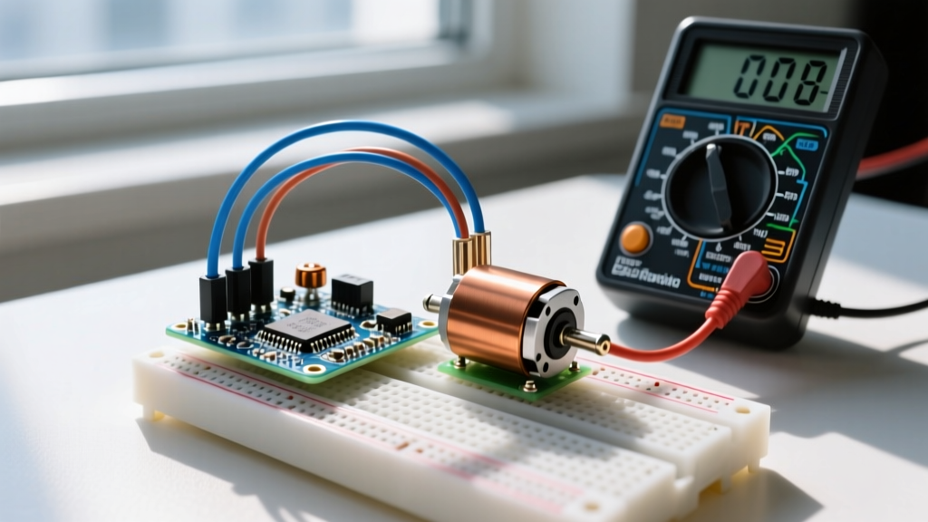
Building a reliable tachometer with Arduino relies on counting digital pulses from a sensor, such as a TCRT5000 optical reflective module or an A3144 Hall effect switch. But when your Serial Monitor spits out erratic or doubled RPM values, the bug is rarely in your C++ code—it is almost always in the physical signal. To properly verify a tachometer circuit, you must measure the sensor's digital pulse train with a multimeter or oscilloscope. A good reading shows clean 0V to 5V square waves with sharp edges; a bad reading shows voltage sag, ground bounce, or excessive rise times. Here is the exact bench procedure to validate your hardware before you waste hours rewriting interrupt logic.
Test Equipment Setup and Safety Categories
Before probing the circuit, configure your digital multimeter (DMM) to capture fast digital transitions. Standard DC voltage mode averages the signal, giving you a useless 2.5V reading for a 50% duty cycle square wave. You need to measure frequency, duty cycle, or capture the absolute minimum and maximum voltages.
Meter Setup Block
- Dial Position: Hz / Duty Cycle (for frequency verification) or DC Volts with Min/Max capture enabled (to verify logic levels).
- Lead Jacks: Black lead to COM, Red lead to V/Ω/Hz.
- Range: Auto-ranging, or manually lock to the 10V DC range to speed up the sampling rate on manual-ranging meters.
Tachometers are frequently bolted to motors. If your motor is powered by mains voltage (e.g., a 120V AC appliance fan or a 240V hardwired HVAC blower), the motor chassis and wiring pose a severe shock and arc flash hazard. Use a minimum CAT II 600V rated multimeter when probing sensors on cord-and-plug appliance motors. If the motor is hardwired into the building's electrical system, you must use a CAT III 600V meter. Never use an unrated CAT I bench meter near mains-powered motor housings—a winding fault could put 120V on the sensor ground, destroying your Arduino and shocking you. Always de-energize the mains motor, verify dead with a non-contact voltage tester, and only re-energize when probes are securely clipped, not hand-held. For full details on measurement categories, refer to the Fluke CAT safety guide.
Probe Placement and Expected Signal Readings
Place your red probe directly on the OUT (or DO) pin of the sensor module header, and the black probe on the module GND pin. Do not probe the Arduino digital pin directly; probing at the sensor isolates whether a fault lies in the sensor itself or in the wiring harness between the sensor and the microcontroller.
Below is the definitive reference table for what your meter or oscilloscope should display when testing a standard 5V open-collector sensor module (like the TCRT5000 or A3144) driven by a motor at a steady speed.
| Test Point / Parameter | Expected "Good" Reading | "Bad" Reading & Root Cause |
|---|---|---|
| Sensor VCC (at module header) | 4.95V – 5.05V | < 4.5V (USB voltage sag or excessive current draw from shared 5V rail) |
| Signal HIGH (Open Collector pulled up) | 4.8V – 5.0V | 2.5V – 3.5V (Missing external pull-up; relying on weak internal 20kΩ Arduino pull-up) |
| Signal LOW (NPN transistor saturated) | 0.05V – 0.2V | > 0.8V (Ground bounce, faulty transistor, or shared ground return carrying high motor current) |
| Pulse Frequency (at 1200 RPM, 1 pulse/rev) | 20.00 Hz ± 0.1 Hz | Erratic / 0 Hz (Misaligned target, wrong threshold potentiometer setting on analog module) |
| Signal Rise Time (Oscilloscope required) | < 2 µs | > 10 µs (Parasitic capacitance from using >24 inches of unshielded ribbon cable) |
Mistakes That Give Misleading RPM Readings
When your hardware readings look terrible, it is usually due to one of three common bench mistakes. Identifying these will save you from chasing software ghosts.
1. Relying on Internal Pull-Up Resistors
The ATmega328P (used in the Arduino Uno and Nano) has an internal pull-up resistor of roughly 20kΩ to 50kΩ. When you use long wires to route a Hall effect sensor from a motor to your breadboard, the wire's parasitic capacitance pairs with that high resistance to form an RC low-pass filter. This rounds off the sharp edges of your square wave. The Arduino interrupt might miss the edge entirely or, worse, double-trigger as the slow voltage slope lingers in the undefined logic region between 1.5V and 3.0V. The Fix: Solder a 4.7kΩ or 10kΩ external pull-up resistor to 5V directly at the sensor end of the cable. This lowers the impedance and sharpens the rise time.
2. Ground Loops and Shared Returns
If your sensor ground wire is daisy-chained with the ground return of a high-current motor driver (like an L298N or a brushed ESC), the PWM switching noise will induce voltage spikes on the ground wire. The sensor LOW state might spike to 1.5V relative to the Arduino's ground. The ATmega328P will interpret this 1.5V spike as a HIGH logic state, effectively doubling your RPM reading. The Fix: Use a star-ground topology. Run a dedicated ground wire from the sensor module directly to the Arduino GND pin, completely bypassing the motor driver's ground path.
3. LM393 Comparator Chatter on Optical Modules
Most cheap TCRT5000 optical modules feature both an Analog Out (AO) and a Digital Out (DO). The DO pin relies on an onboard LM393 comparator and a blue trimmer potentiometer. If the potentiometer is misadjusted, or if the reflective tape on your flywheel is slightly wrinkled, the comparator will "chatter" (oscillate rapidly) at the exact edge of the reflective boundary. This can send 50 extra micro-pulses per revolution, making your Arduino think the motor is spinning at 10,000 RPM when it is actually at 500 RPM. The Fix: Connect your Arduino to the AO pin and use analogRead() with a software Schmitt trigger in your code, or carefully tune the DO trimmer while monitoring the signal on an oscilloscope until the chatter disappears. For a deeper dive into optical sensor theory, see this guide on sensor integration.
Validating Hardware Pulses Against Arduino Interrupts
Once your multimeter confirms clean 0V-5V square waves with the correct frequency, you must prove the Arduino is counting them accurately. The most robust method for tachometry is measuring the time interval between pulses using micros(), rather than counting pulses over a fixed one-second window. This provides instant RPM updates even at very low speeds.
Upload the following code to your Arduino. This snippet includes the necessary volatile keywords and critical sections to prevent data tearing when reading 32-bit variables inside the main loop.
volatile unsigned long lastMicros = 0;
volatile unsigned long pulseInterval = 0;
const byte interruptPin = 2; // Pin 2 or 3 on Uno/Nano

void setup() {
  Serial.begin(115200);
  pinMode(interruptPin, INPUT_PULLUP); // Use external 4.7k if wires are long
  attachInterrupt(digitalPinToInterrupt(interruptPin), countPulse, FALLING);
}

void loop() {
  noInterrupts();
  unsigned long currentInterval = pulseInterval;
  interrupts();

  if (currentInterval > 0) {
    // Calculate RPM: (60 seconds * 1,000,000 micros) / (interval * pulses per rev)
    float rpm = 60000000.0 / (currentInterval * 1.0); // Assuming 1 pulse/rev
    Serial.print("RPM: ");
    Serial.println(rpm, 1);
  } else {
    Serial.println("RPM: 0.0 (Motor stopped or no signal)");
  }
  delay(250);
}

void countPulse() {
  unsigned long now = micros();
  pulseInterval = now - lastMicros;
  lastMicros = now;
}
Verification Step: To test this without a motor, use a function generator (or a second Arduino generating a 50 Hz PWM signal) and feed it into Pin 2. A 50 Hz signal simulates 50 pulses per second, which equals exactly 3000 RPM (assuming 1 pulse per revolution). If your Serial Monitor reads 3000.0 RPM, your hardware and software are perfectly synchronized. If it reads 6000.0 RPM, you have accidentally set the interrupt to trigger on CHANGE instead of FALLING, or you are suffering from switch bounce. For more on interrupt handling, consult the official Arduino attachInterrupt documentation.