
Architectural Overview: Why ESP32 and MQTT?
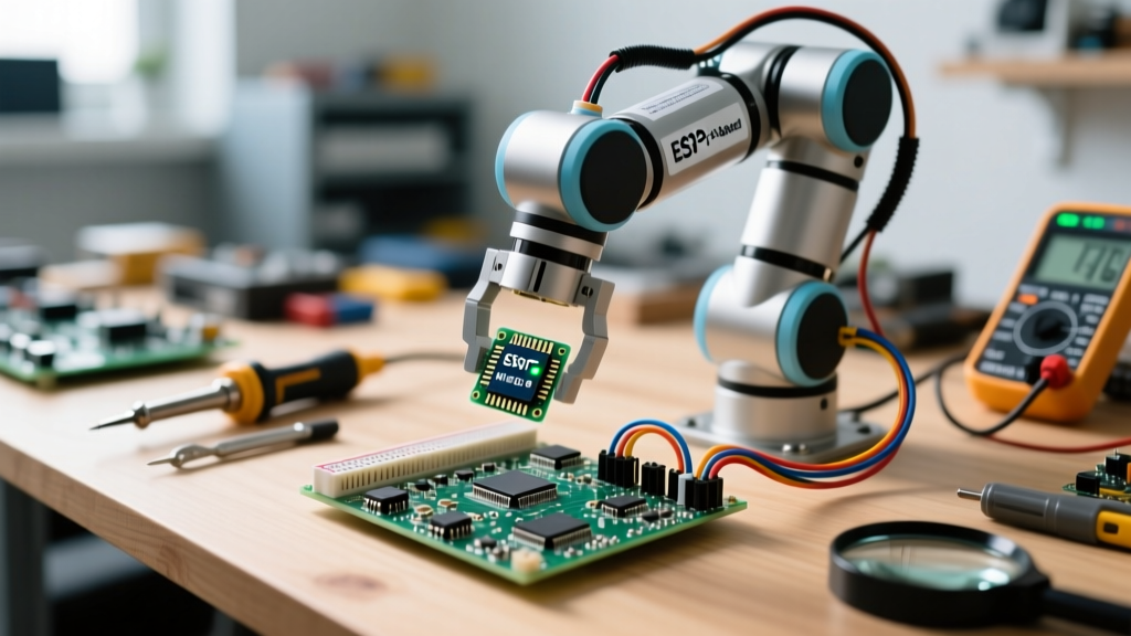
Learning how to build a robotic arm is a foundational milestone in robotics, but transforming it into an IoT-connected device elevates it from a desk toy to a scalable industrial prototype. By utilizing the ESP32 microcontroller, we leverage dual-core processing, native Wi-Fi, and Bluetooth capabilities. This allows the arm to operate untethered, receiving low-latency commands over a local network or the cloud via the MQTT (Message Queuing Telemetry Transport) protocol.
Unlike traditional UART or Bluetooth HC-05 setups that require direct line-of-sight or paired connections, an MQTT-based architecture uses a publish/subscribe model. This means you can control the robotic arm from a web dashboard, a mobile app, or even integrate it with Home Assistant using Node-RED, all while the ESP32 handles the real-time inverse kinematics and PWM generation locally.
Bill of Materials (BOM) for a 4-DOF IoT Arm
To ensure high torque and network reliability, we must select components that can handle both mechanical stress and continuous data polling. Below is the optimized BOM for a 4-Degree-of-Freedom (DOF) arm.
| Component | Model / Specification | Purpose | Approx. Cost |
|---|---|---|---|
| Microcontroller | ESP32 DevKit V1 (30-pin) | Wi-Fi/MQTT processing & I2C master | $6.00 |
| Servo Driver | PCA9685 16-Channel PWM | Offloads PWM generation via I2C | $3.50 |
| Servos (x4) | MG996R (Metal Gear, 13kg-cm) | Joint actuation (Base, Shoulder, Elbow, Gripper) | $18.00 |
| Power Supply | 5V 10A Switching PSU (Buck) | Dedicated high-current servo power | $12.00 |
| Chassis | 3D Printed PETG / PLA | Structural links and base | $10.00 |
Mechanical Assembly and 3D Printing Tolerances
When designing or printing the chassis for your robotic arm, material selection dictates the lifespan of your joints. While PLA is sufficient for the heavy base (providing a low center of gravity), the moving links and joint brackets should be printed in PETG or ABS. PLA is prone to creep under continuous mechanical load, which will cause your arm to drift over time.
Managing Servo Horn Alignment
A common failure mode in DIY robotic arms is stripping the servo splines. Before attaching the MG996R servo horns to the 3D printed joints, you must center the servos programmatically. Upload a simple sketch that commands the PCA9685 to output a 1.5ms pulse (90 degrees). Attach the horn only when the joint is mechanically centered. This ensures you have equal rotational travel in both directions and prevents the servo from stalling against the physical limits of the PETG bracket.
Power Distribution: Eliminating the ESP32 Brownout Failure
The most critical hurdle when figuring out how to build a robotic arm with high-torque servos is power management. The MG996R servo has a stall current of roughly 2.5 Amps at 6V. If your 4-DOF arm moves multiple joints simultaneously, the instantaneous current draw can easily spike past 8 Amps.
If you attempt to power the ESP32 and the servos from the same USB port or a standard 5V 2A wall adapter, you will trigger the ESP32's internal brownout detector. According to the Espressif Brownout Detector Docs, the chip will reset if the 3.3V rail sags below ~2.43V, which happens when high-current servo spikes collapse the voltage on shared power rails.
The Decoupling Solution
- Servo Power: Wire the 5V 10A PSU directly to the V+ and GND terminal blocks on the PCA9685 board.
- Logic Power: Power the ESP32 via its USB port or a dedicated 3.3V LDO regulator connected to the 5V rail.
- Common Ground: You must connect the GND of the 10A PSU to the GND of the ESP32. Without a common ground reference, the I2C signals from the ESP32 to the PCA9685 will fail, resulting in erratic servo behavior.
IoT Firmware: MQTT Payloads and WebSocket Control
To control the arm over the network, we use the PubSubClient library for MQTT. As detailed in the Random Nerd Tutorials ESP32 MQTT Guide, MQTT is lightweight and perfect for IoT robotics.
Instead of sending raw angles, we structure our IoT commands using JSON payloads. This allows us to send complex instructions, such as speed profiles or multi-joint coordinated movements, in a single packet.
JSON Payload Structure for Joint Actuation
Subscribe the ESP32 to the topic robot/arm/control. A typical incoming payload looks like this:
{
  "joint": "shoulder",
  "angle": 115,
  "speed": 50
}
The ESP32 parses this JSON using the ArduinoJson library. The speed parameter allows the firmware to implement a software ramping function, moving the servo incrementally rather than snapping to the target angle instantly. This reduces mechanical shock and current spikes.
Wiring the PCA9685 to the ESP32
The PCA9685 communicates via I2C. While the ESP32 has internal pull-up resistors, the physical distance between the MCU and the servo driver board can introduce noise, especially in an environment with high-current PWM switching.
Referencing the Adafruit PCA9685 Guide, ensure your I2C wires (SDA and SCL) are kept under 10cm. If you must route them further, solder 4.7kΩ pull-up resistors to the 3.3V line on the I2C bus. Set the PCA9685 PWM frequency to exactly 50Hz (a 20ms period) in your setup function, as standard analog servos expect a pulse width between 1ms and 2ms within that 20ms window.
Calibration, Jitter, and Real-World Troubleshooting
Even with perfect code, physical robotic arms often suffer from servo jitter. Here is a diagnostic framework for troubleshooting IoT-connected arms:
- Network Latency Jitter: If the arm stutters only when receiving MQTT commands, check your Wi-Fi router's 2.4GHz channel congestion. Move the ESP32 to a less crowded channel or implement a local MQTT broker (like Mosquitto on a Raspberry Pi) rather than relying on a cloud broker like AWS IoT or HiveMQ to eliminate WAN latency.
- Electrical Noise Jitter: If the servos jitter randomly even when idle, you likely have a grounding loop or insufficient decoupling capacitance. Solder a large electrolytic capacitor (e.g., 1000µF 10V) directly across the V+ and GND terminals of the PCA9685 to absorb transient current demands.
- Potentiometer Wear: MG996R servos use cheap internal potentiometers for position feedback. If a specific joint constantly hunts back and forth around its target angle, the internal pot is degraded. Replace the servo or upgrade to a digital serial bus servo (like the LewanSoul LX-16A) which uses magnetic encoders instead of physical wipers.
Conclusion
Understanding how to build a robotic arm with IoT capabilities bridges the gap between embedded systems and cloud computing. By respecting the electrical realities of high-torque servos, isolating your power domains, and utilizing MQTT for scalable communication, your ESP32 robotic arm will serve as a robust platform for computer vision integration, automated sorting, and remote telepresence experiments.