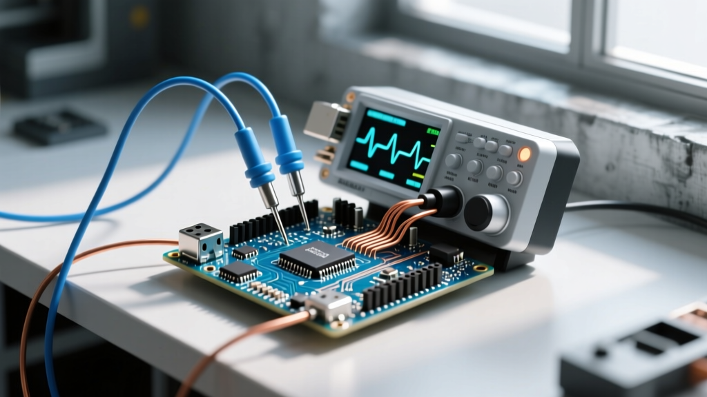

If you are searching for an 'Arduino PC oscilloscope' solution, you are likely trying to debug timing-critical signals—like I2C buses, SPI clocks, or AC zero-cross detection—and have realized the Arduino Serial Plotter is inadequate. The direct answer: do not use the Arduino's internal 10-bit ADC as a makeshift oscilloscope for anything beyond slow analog sensors. Instead, pair your microcontroller with a dedicated USB PC oscilloscope (such as a PicoScope 2000 series or Digilent Analog Discovery 3) to achieve real bandwidth, hardware triggering, and accurate voltage scaling.
The 'Arduino as Oscilloscope' Hack vs. Real USB PC Scopes
A common forum hack involves writing a sketch that runs analogRead() in a tight loop and pushes the data over serial to a Processing or Python GUI. While this costs zero dollars, it is fundamentally limited. The ATmega328P's ADC tops out at roughly 15 kS/s (kilosamples per second) under ideal conditions, giving you a usable bandwidth of about 3 kHz to 5 kHz before aliasing destroys your waveform. Furthermore, it lacks hardware triggering, meaning you cannot capture a single-shot event like a relay bounce or a brownout reset.
A true USB PC oscilloscope offloads the sampling to a dedicated FPGA and high-speed ADC. Devices like the PicoScope 2204A offer 100 MS/s sampling rates and 25 MHz bandwidth, while the Digilent Analog Discovery 3 provides 14-bit resolution for precise analog debugging. These tools allow you to set precise trigger edges, decode serial protocols automatically, and measure microsecond-level rise times that the Arduino's internal ADC simply smears into a flat line.
Safety, CAT Ratings, and Pre-Flight Meter Setup
When your Arduino project interfaces with mains voltage (e.g., a DIY reflow oven, a motor controller, or a solid-state relay driver), safety becomes the primary constraint. Standard USB PC oscilloscopes are not CAT rated for direct mains connection. The ground clip on your scope probe is tied directly to your PC's earth ground via the USB shield. If you clip that ground to a mains-referenced node on your breadboard, you will create a dead short through your PC, likely destroying the motherboard and creating a severe shock and fire hazard.
To measure mains-referenced signals safely, you must use a high-voltage differential probe rated for at least CAT II (for appliance-level mains) or CAT III (for distribution panels). Never rely on standard passive 1X/10X probes for mains work. For the isolated low-voltage DC side of your Arduino circuit, standard CAT I or un-rated PC scope probes are acceptable, provided you verify isolation first. See the Fluke guide on electrical safety categories for detailed boundary definitions.
Before connecting your PC oscilloscope's ground clip to your Arduino circuit, you must verify that your power supply provides proper galvanic isolation. Use a digital multimeter (DMM) for this pre-flight check.
- Dial Position: V~ (AC Voltage) to check for mains leakage; V⎓ (DC Voltage) to verify the logic rail.
- Lead Jacks: Black lead in COM, Red lead in V/Ω/Hz.
- Range: Auto-ranging enabled. If manual, set to 200V AC for isolation checks, and 20V DC for logic rails.
- Procedure: Measure between the Arduino GND pin and a known earth ground (like a bench ground strap or metal conduit). If you read >1V AC, your power supply lacks proper isolation. Do not connect the PC scope ground clip until the supply is replaced.
Probe Placement and Expected Signal Readings
Once isolation is verified, you can connect the PC oscilloscope. Proper probe placement is critical; always place the ground spring or clip as close to the measurement point as possible to minimize loop inductance, which causes ringing on fast edges. Below is the expected reading table for a typical Arduino-based AC zero-cross detection (ZCD) and triac drive circuit.
| Test Point | Probe Setup & Placement | Expected Good Reading (Numerical) | Bad Reading / Failure Mode |
|---|---|---|---|
| 5V Logic Rail | DC Coupling, 2V/div. Probe tip on 5V pin, ground on adjacent GND. | 4.95V - 5.05V DC, ripple < 30mV p-p. | 4.2V (USB brownout) or >60mV ripple (failing linear regulator). |
| ZCD Interrupt (Pin D2) | DC Coupling, 5V/div, 10ms/div. Probe tip on D2, ground on GND. | 0V to 5V square wave, 120Hz (for 60Hz mains), rise time < 5µs. | Floating 2.5V (missing internal pull-up) or 60Hz (missed half-cycles). |
| Optocoupler LED Anode | DC Coupling, 2V/div. Probe tip on anode, ground on GND. | 1.2V forward drop when driven HIGH, 0V when LOW. | 0V always (blown LED) or 3.3V/5V (series current-limiting resistor open). |
| Triac Gate PWM (Pin D9) | DC Coupling, 5V/div, 2ms/div. Probe tip on D9, ground on GND. | 5V pulses, 1kHz carrier, duty cycle varying 10-90%. | Flat 5V (software stuck HIGH, triac shorted) or noisy/ringing edges. |
Step-by-Step Capture: Tuning the PC Scope Software
Capturing a clean zero-cross interrupt requires setting up the software trigger correctly. If you rely on auto-triggering, the scope will constantly roll, making it impossible to measure the exact phase delay between the AC zero-cross and your Arduino's triac firing angle.
- Set the Timebase: For a 60Hz AC signal, one full cycle is 16.67ms. Set your horizontal timebase to 5ms/div to capture roughly two full cycles across a 10-division screen.
- Configure the Trigger: Switch Channel A (connected to the ZCD pin) to 'Edge Trigger'. Set the trigger level to 2.5V (the midpoint of the 5V logic swing) and select 'Rising Edge'. Set the trigger mode to 'Normal' or 'Single' rather than 'Auto'.
- Adjust Voltage Scale: Set Channel A to 2V/div with a DC offset of -2V. This places the 0V baseline near the bottom of the screen and the 5V peak near the top, maximizing vertical resolution.
- Enable Measurements: Use the software's automated cursors to measure the 'Delay' between Channel A (ZCD pulse) and Channel B (Triac PWM start). This delay is your firing angle, which should numerically match the
delayMicroseconds()value in your Arduino sketch.
Common Mistakes That Give Misleading Readings
Even with a high-end USB PC oscilloscope, operator error can render your data useless. Here are the most frequent mistakes that yield misleading readings when debugging microcontrollers:
- Probe Attenuation Mismatch: If your physical probe switch is set to 10X, but the PC software channel is configured to 1X, your voltage readings will be exactly one-tenth of their actual value. You will see a 0.5V logic signal and assume your Arduino is browning out, when in reality it is outputting a healthy 5V. Always verify the physical switch matches the software dropdown.
- Ground Loop Shorts: As mentioned in the safety section, connecting the scope ground clip to a non-ground reference (like the source pin of a high-side MOSFET or a mains-live node) creates a short circuit. This will pull the node to earth ground, completely altering the circuit's behavior and giving you a 'flatline' reading that looks like a component failure, when it is actually your probe destroying the circuit state.
- Aliasing from Slow Timebases: If you are looking for high-frequency noise on a 5V rail but have your timebase zoomed out to 1 second/div, the scope's sample rate drops to maintain the memory buffer. A 500 kHz switching regulator ripple will alias down and appear as a slow, 2Hz sine wave. Always zoom in to the fastest timebase possible when hunting for power supply noise.
- Ignoring Probe Compensation: Before measuring fast digital edges (like SPI clocks), connect your probe to the scope's built-in 1kHz square wave calibration output. If the square wave corners look rounded or exhibit overshoot spikes, use a small jeweler's screwdriver to adjust the trimmer capacitor on the probe body. An uncompensated probe will show false overshoot on your Arduino's GPIO pins, leading you to add unnecessary series termination resistors.


