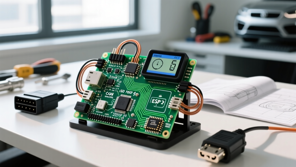
The Allegro A4988 is a dual full-bridge driver IC designed specifically to drive bipolar stepper motors. While newer silent drivers like the TMC2209 have claimed the high-end 3D printing market, the A4988 stepper motor controller remains the undisputed budget king for CNC routers, camera sliders, and automated dispensers in 2026, often costing under $1.50 per module. It delivers up to 2A per phase (absolute max) and supports microstepping down to 1/16th of a full step.
However, the A4988 is unforgiving of poor thermal management and incorrect motor pairing. If you push a high-inductance motor past its continuous current limits without active cooling, the IC will thermally throttle or fail. This guide covers exactly how to size a bipolar stepper for the A4988, how to wire the module safely, and how to diagnose the specific failure signatures this driver exhibits under load.
Sizing Bipolar Steppers for the A4988 Controller
The most common mistake makers make with the A4988 is pairing it with a high-current NEMA 17 motor (rated at 1.7A or 2.0A) and assuming the driver can handle it continuously. The A4988 datasheet specifies a 2A absolute maximum peak current, but its continuous thermal limit is 1A per phase without a heatsink, and 1.5A per phase with a heatsink and active forced air.
Below is a data-dense selection table matching common NEMA 17 stepper motors to the A4988's real-world thermal constraints.
| Motor Model (NEMA 17) | Rated Current / Phase | Holding Torque | Inductance | A4988 Compatibility |
|---|---|---|---|---|
| 17HS4012 | 1.2A | 22 Ncm (31 oz-in) | 2.8 mH | Ideal. Runs cool with basic heatsink. |
| 17HS4401 | 1.7A | 40 Ncm (56 oz-in) | 4.0 mH | Margin. Requires active fan cooling; set Vref to 1.2A max. |
| 17HS8401 | 0.4A | 14 Ncm (20 oz-in) | 1.6 mH | Overkill. Runs cold, but lacks torque for heavy loads. |
| 17HS4802 (High Inductance) | 1.2A | 45 Ncm (63 oz-in) | 8.5 mH | Avoid. High inductance causes severe torque drop-off at speed. |
Worked Load Example: CNC Z-Axis Lift
Suppose you are building a CNC router Z-axis that must lift a 2.5 kg spindle assembly using an 8mm lead screw with a 2mm pitch.
- Force required: 2.5 kg × 9.81 m/s² = 24.5 N.
- Torque at screw: (Force × Pitch) / (2π × Efficiency). Assuming 90% efficiency: (24.5 × 0.002) / (6.28 × 0.9) = 0.0087 Nm (8.7 mNm).
- Safety Margin: Multiply by 3x to account for acceleration, friction, and cutting forces = ~26 mNm required.
The 17HS4012 provides 22 Ncm (220 mNm) of holding torque, which is nearly 10x the required dynamic torque, ensuring it won't stall during rapid plunges. More importantly, its 1.2A current rating keeps the A4988 safely within its continuous thermal envelope, preventing mid-print thermal shutdown.
Wiring, Terminals, and Microstepping Configuration
The standard A4988 carrier board breaks out 16 pins. Miswiring the logic and motor power rails is the fastest way to brick the module.
Terminal Identification
- VMOT & GND (Power): Motor supply voltage (8V to 35V). Critical: You must place a 100µF electrolytic capacitor directly across these pins to absorb inductive voltage spikes.
- VDD & GND (Logic): Logic supply (3V to 5.5V). Tie this to your Arduino/ESP32 5V or 3.3V pin.
- 1A, 1B, 2A, 2B: Motor coil outputs. To identify your motor's coils, disconnect the motor from power and use a multimeter in continuity mode. Pins that show a short (low resistance, typically 1-5 ohms) are one coil pair. The remaining two pins are the second coil pair.
- STEP & DIR: STEP requires a rising edge pulse to move one microstep. DIR sets rotation (High = CW, Low = CCW).
- SLP (Sleep) & RST (Reset): SLP must be High to operate. RST must be High to operate. If floating, tie them together or pull them to VDD.
- ENABLE: Active Low. Pull to GND to enable the driver, High to disable.
Microstepping Jumper Mapping
The A4988 uses three pins (MS1, MS2, MS3) to set the microstepping resolution. Leaving them floating defaults to full-step mode. For 3D printing and CNC, 1/16th stepping is standard for smooth motion.
| Resolution | MS1 | MS2 | MS3 |
|---|---|---|---|
| Full Step | Low | Low | Low |
| Half Step | High | Low | Low |
| 1/4 Step | Low | High | Low |
| 1/8 Step | High | High | Low |
| 1/16 Step | High | High | High |
Load Profiles: Which Motor and Driver Combination Wins?
While the A4988 is excellent for open-loop positioning, it is not the only motion control topology available. When designing a system, you must match the motor type to the load profile. Below is a comparison of the three most common low-cost actuator types to help you decide if a bipolar stepper driven by an A4988 is actually what your project demands.
| Feature | Bipolar Stepper (A4988) | Unipolar Stepper (ULN2003) | Hobby Servo (MG996R) |
|---|---|---|---|
| Torque Curve | Flat at low speed, drops sharply at high RPM. | Lower overall torque, drops at high RPM. | Peak torque at stall, drops as speed increases. |
| Control Needs | STEP/DIR pulses, requires H-bridge driver. | Sequential logic pulses, simple transistor array. | PWM signal (50Hz, 1-2ms pulse width). |
| Position Feedback | Open-loop (assumes position via step counting). | Open-loop. | Closed-loop (internal potentiometer, limited to 180°). |
| Typical Cost (2026) | $12 - $18 (Motor + Driver) | $5 - $8 (Motor + Driver board) | $8 - $15 (Integrated unit) |
| Best Application | CNC axes, 3D printer extruders, linear actuators. | Low-load dials, basic educational robots. | RC vehicle steering, robotic arm joints. |
Verdict: Choose the A4988 and a bipolar stepper when you need continuous rotation, high holding torque at zero speed, and precise linear translation via lead screws. Choose a servo if your load requires high torque across a limited angular range (under 360°) and you need built-in position correction without adding external encoders.
Diagnosing Failure Signatures: Hum, Overheat, and Stall
The A4988 lacks the advanced diagnostic registers found in modern SPI-driven Trinamic chips. When it fails, it communicates through physical symptoms. Here is how to decode them.
1. Motor Hums but Will Not Rotate
Cause: The current limit potentiometer on the A4988 is set too low, or the step pulse frequency is too high for the supply voltage.
Fix: Measure the voltage at the Vref test point. The formula is Vref = Current Limit / 2. For a 1.2A motor, set Vref to 0.6V. If Vref is correct, lower the STEP frequency in your firmware or increase VMOT (e.g., from 12V to 24V) to push current through the coil inductance faster.
2. Driver Overheats and Shuts Down Mid-Job
Cause: Thermal throttling. The A4988 has internal over-temperature shutdown. If you are pulling 1.5A without a fan, the silicon junction will hit 165°C and cut power.
Fix: Add a 5V 40mm fan blowing directly across the heatsink. If the load allows, reduce the current limit via the Vref pot. Alternatively, upgrade to a DRV8825 or TMC2209 driver, which have higher thermal tolerances and better heat dissipation paths.
3. Erratic Stepping or Fried IC
Cause: Missing or undersized decoupling capacitor on VMOT. Stepper motors are massive inductors. When the A4988's internal MOSFETs switch off, the collapsing magnetic field sends a voltage spike back into the VMOT rail. If this spike exceeds 35V, it punches through the IC's die.
Fix: Never operate an A4988 without a minimum 47µF (ideally 100µF) low-ESR electrolytic capacitor placed as close to the VMOT and GND pins as physically possible. Soldering it directly to the header pins on the underside of the board is the most reliable method.
4. Mid-Band Resonance (Stalling at Specific Speeds)
Cause: Bipolar steppers suffer from a natural resonance frequency, usually between 100 and 300 steps per second, where torque drops to near zero. The A4988's standard chopper drive cannot electronically dampen this.
Fix: In your firmware (like Marlin or GRBL), accelerate quickly through the 100-300 steps/sec zone. If the application requires operating continuously in this band, add a mechanical damper to the motor shaft, or switch to a driver featuring SpreadCycle chopper technology which actively mitigates resonance.
For deeper architectural insights into stepper motor topologies and chopper drive theory, the All About Circuits stepper motor guide provides excellent foundational physics. Always cross-reference your specific motor's datasheet for inductance values, as high-inductance motors will severely bottleneck the A4988's high-speed performance regardless of how well you wire the system.