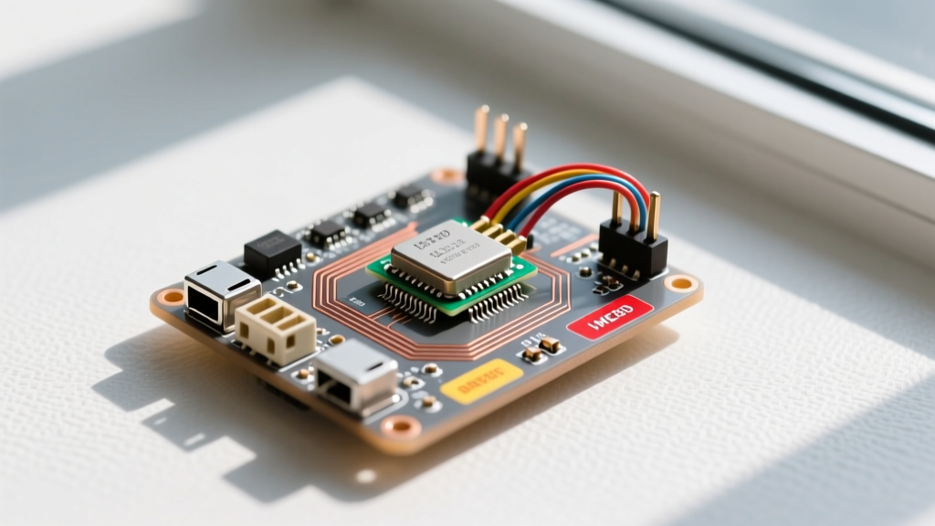
When a high-power component like a TO-220 voltage regulator or MOSFET starts cooking itself inside a sealed project enclosure, guessing your cooling requirements is a recipe for silicon death. To keep a linear regulator dissipating 18W alive in a 45°C ambient environment, you need two things: a precision circuit for temperature sensor feedback to monitor the case, and a heatsink with a thermal resistance ($R_{\theta SA}$) of 1.94 °C/W or lower, such as the Wakefield Engineering 640K.
This guide walks through the exact electrical design for high-accuracy thermal monitoring, the junction-to-ambient math required to size your cooling hardware, and the physical failure signatures that tell you your thermal design is failing before the silicon actually melts.
Building a Precision Circuit for Temperature Sensor Feedback
While a cheap 10k NTC thermistor in a voltage divider seems tempting for thermal monitoring, the ESP32’s internal ADC is notoriously non-linear, often drifting by 2-3°C across the operating range. For active thermal management—where you are triggering PWM fan curves or throttling loads based on exact thresholds—you need digital precision.
The TI TMP117 provides ±0.1°C accuracy over I2C. However, simply plugging in a breakout board isn't enough; the circuit for the sensor must be designed to couple thermally with the target IC while rejecting electrical noise.
| Component | Value / Part Number | Purpose |
|---|---|---|
| U1: Temp Sensor | TI TMP117 (WSON-8) | High-accuracy digital thermal readout |
| R1, R2: Pull-ups | 10kΩ 1% 0402 | I2C SDA/SCL bus conditioning |
| C1: Decoupling | 100nF X7R 0402 | Local charge storage (place <2mm from VCC) |
| C2: Bulk | 4.7µF 0603 | Low-frequency noise rejection |
Wire the I2C lines to your ESP32 (e.g., GPIO 21 for SDA, GPIO 22 for SCL on an ESP32 DevKit v1). Keep the I2C traces under 30cm to avoid bus capacitance issues, and route them away from high-current switching nodes that could induce thermal-reading glitches via EMI.
Thermal Path Math: Calculating Junction-to-Ambient Resistance
You cannot pick a heatsink without knowing your wattage and thermal resistance network. Heat flows from the silicon junction ($T_J$) through the case ($R_{\theta JC}$), through the mounting interface ($R_{\theta CS}$), into the heatsink ($R_{\theta SA}$), and finally to ambient air ($T_A$). TI's application note on thermal metrics details how these resistances add up in series.
The governing equation is:
$T_J = T_A + P_D \times (R_{\theta JC} + R_{\theta CS} + R_{\theta SA})$
Worked Example: You are using an LM317 in a TO-220 package to drop 24V down to 12V to power a 1.5A LED array.
Power Dissipated ($P_D$) = $(24V - 12V) \times 1.5A = 18W$.
Max Junction Temp ($T_J$) = 125°C (absolute limit), but we will target 105°C for reliability.
Ambient Temp inside Enclosure ($T_A$) = 45°C.
We need to find the maximum allowable heatsink resistance ($R_{\theta SA}$):
- Allowable $\Delta T = 105°C - 45°C = 60°C$.
- Total allowed thermal resistance $R_{\theta JA} = 60°C / 18W = 3.33 °C/W$.
- TO-220 $R_{\theta JC}$ (Junction-to-Case) = 2.0 °C/W (from the datasheet).
- Interface pad $R_{\theta CS}$ (Case-to-Sink) = 0.5 °C/W (using a Bergquist Sil-Pad 400V0S).
Solving for the heatsink:
$R_{\theta SA} = 3.33 - 2.0 - 0.5 = 0.83 °C/W$.
Reading Derating Curves and Spotting Failure Signatures
Datasheets include a "Power Derating Curve" graph, but hobbyists frequently misinterpret it. A derating curve for a TO-220 package usually shows it can handle 20W at 25°C, dropping to 0W at 125°C. This curve assumes an infinite heatsink (case temperature held perfectly at ambient). In reality, without a heatsink, a bare TO-220 has an $R_{\theta JA}$ of about 50 °C/W. At 18W, a bare package would instantly hit $25°C + (18 \times 50) = 925°C$ and vaporize. Always shift the derating curve based on your actual calculated $R_{\theta JA}$.
How hot is too hot? While 125°C is the silicon limit, operating above 85°C case temperature drastically accelerates three specific failure signatures:
- Thermal Hiccup Oscillation: The IC hits its internal thermal shutdown threshold (usually ~150°C junction), cuts output, cools for two seconds, and turns back on. Your multimeter will read an average voltage, but an oscilloscope will show a violent 12V-to-0V sawtooth wave every few seconds.
- Solder Creep and Cracking: The copper PCB traces and the silicon die expand at different rates (Coefficient of Thermal Expansion mismatch). Over thousands of heat/cool cycles, this mechanical stress causes dull, cracked rings around the TO-220 lead solder joints, leading to intermittent high-resistance connections.
- Electromigration: At sustained temperatures above 100°C, metal atoms inside the silicon's microscopic traces literally migrate due to electron wind. This permanently increases the internal resistance of the component over months, resulting in unexplained voltage drops and increased heat generation—a runaway thermal failure loop.
Heatsink Selection, Airflow, and Enclosure Penalties
Returning to our 18W LM317 example, we need an $R_{\theta SA}$ of 0.83 °C/W or lower. According to heatsink selection principles, natural convection (passive cooling) relies entirely on surface area and fin geometry.
| Strategy | Hardware | Effective $R_{\theta SA}$ | Verdict |
|---|---|---|---|
| Passive Extruded | Wakefield 640K (Large finned) | ~1.6 °C/W | Fails our 0.83 °C/W requirement in still air. |
| Active Extruded | Wakefield 640K + 40mm Fan | ~0.7 °C/W | Passes. Forced air cuts resistance by >50%. |
| Chassis Mount | Bolting to 3mm aluminum box | ~2.5 °C/W | Fails unless the entire box is heavily finned. |
What Airflow and Enclosure Changes Buy You:
Sealing your project in an IP65 plastic enclosure traps heat, easily adding 15°C to your internal $T_A$. Cutting two 40mm louvered vents on opposite sides (bottom intake, top exhaust) leverages the stack effect and buys you back roughly 10°C of thermal headroom for free. If you must seal the enclosure, adding a Sunon MagLev 40x40x10mm fan (MF40101VX) blowing directly across the Wakefield 640K fins drops the thermal resistance from 1.6 °C/W down to 0.7 °C/W, safely clearing our 0.83 °C/W math requirement.
The Thermal Decision Tree: Sizing Your Cooling Solution
Stop guessing heatsink sizes. Use this decision path to terminate your design with a concrete hardware pick based on your calculated power dissipation ($P_D$).
| Condition | Action & Hardware Pick |
|---|---|
| $P_D < 1.5W$ | No Heatsink. Rely on the bare TO-220 leads and PCB copper pour. Ensure 2oz copper on the drain/tab pad. |
| $1.5W \le P_D \le 5W$ | Clip-on Board Level. Use the Aavid Thermalloy 577102B03300G. Spring-clip attachment, no drilling required. $R_{\theta SA} \approx 14 °C/W$. |
| $5W < P_D \le 12W$ | Medium Extruded Passive. Use the Ohmite 590-1 or similar 25mm finned sink. Bolted with isolating pad. $R_{\theta SA} \approx 4.0 °C/W$. |
| $P_D > 12W$ (Our 18W scenario) | Large Extruded + Active Airflow. Use the Wakefield Engineering 640K paired with a Sunon MF40101VX 40mm fan. Apply Arctic Silver 5 thermal compound using the 3mm 'pea' method to ensure complete coverage without squeezing out onto the PCB. Target $R_{\theta SA} < 1.0 °C/W$. |
For our specific 18W, 45°C ambient scenario, the concrete pick is the Wakefield 640K with a Sunon 40mm fan. Build your TMP117 I2C circuit, mount it adjacent to the regulator with thermal via stitching, and program your ESP32 to ramp the fan PWM from 20% to 100% as the sensor crosses 65°C. This guarantees the junction stays safely under 105°C, eliminating thermal hiccup and solder creep for the life of the project.